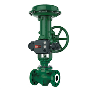
Safety Valve

Safety Valve

Safety Valve

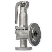
Safety valve is a valve that acts as a protection of equipment from exploding or damaging and it is mainly installed in pressure vessels such as chemical plants, electric power boilers, and gas storage tanks.
Safety Valve is a type of valve that automatically actuates when the pressure of inlet side of the valve increases to a predetermined pressure, to open the valve disc and discharge the fluid (steam or gas); and when the pressure decreases to the prescribed value, to close the valve disc again. Safety valve is so-called a final safety device which controls the pressure and discharges a certain amount of fluid by itself without any electric power support.
Safety valve support not only the safety of the energy industry but also the safety and security of our life.

Start to Discharge Pressure

The inlet pressure at which the safety valve actually starts to discharge and outflow of an extremely small quantity of fluid (steam or gas) are detected at the outlet. The extremely small quantity means a minimum amount of visually or audibly detectable steam, or a minimum amount of gas that can be detected audibly or by using a soap solution. The outflow does not mean the leakage from the valve seat.

Opening Pressure

The inlet pressure at which the valve disc “Pops.” The opening pressure is also called “popping pressure.” “Popping” is an action of discharging fluid inside the valve due to the sudden rise of the valve disc.

Set Pressure

The opening pressure or start to discharge pressure determined in designing.

Closing Pressure

The inlet pressure fell down to the level at which the valve disc and the valve seat are in contact and the lift becomes zero. It is also called “reseating pressure.”

Blowdown

The difference between opening pressure or start to discharge pressure and closing pressure

Over Pressure

The increasing pressure exceeds the set pressure of the safety valve.

Allowable Over Pressure

The overpressure within the allowable range.

Coefficient of Discharge

The coefficient used to calculate the actual discharge capacity from the theoretical discharge capacity. The coefficient is the ratio between the two capacities, and it counts the frictional resistance.

Certified Derated Coefficient of Discharge

The coefficient of discharge to be applied to calculate the certified capacity.

Flow Rating Pressure

The inlet pressure is taken as the basis for determining the certified capacity of the safety valve, which is the sum of the set pressure and the allowable overpressure.

Back Pressure

The pressures existing at the outlet of the safety valve. There are two types as the following: (a) Accumulated back pressure: The pressure existing at the outlet of a safety valve caused by the resistance of the outlet side when the safety valve has been relieved. (b) Existing back pressure: The pressure which has already been superimposed at the outlet before the safety valve is relieved.

Theoretical Discharge Capacity

The discharge capacity calculated supposing that the fluid is free from friction and its flow rate coefficient is 1, and that the valve discharges the ideal gas of fixed specific heat with isentropic change.

Lift

The amount of travel, in the axial direction of the valve or valve rod, away from the closed position to the opened position during discharge of the safety valve

Safety valves protect steam systems and tanks from excess pressure. As they are often the last link in the safety chain, they must remain operational in all conditions.
Safety valves discharge water vapor, neutral gas, steam, and fluid in the event of excess pressure. As soon as normal operating conditions are restored, they close and do not release any more medium.

Feature

Full bore type

  • Flanged
  • Cast Iron
  • Closed type

Application

  • Steam
  • Air
  • Other non-dangerous fluids

Working pressure

  • 0.045 – 1.6 MPa (20-100A) , 0.045 – 1.25 MPa (125A) , 0.045 – 1.0 MPa (150A) , According to PT rating

Max Temperature

  • 250 degree C

Body

  • Cast Iron

Spring chamber

  • Ductile Cast Iron

Valve

  • Stainless steel

Valve seat

  • Stainless steel
WAFER STYLE BUTTERFLY VALVE

HIGH PERFORMANCE WAFER STYLE BUTTERFLY VALVE SAMSON

HIGH-PERFORMANCE WAFER STYLE BUTTERFLY VALVE

A butterfly valve is a shut-off valve with a relatively simple construction. In the closed position, the disc blocks the valve bore while in open position, the disc is turned to allow flow. A quarter turn takes the valve from fully open to the fully closed position or the opposite, and thus the butterfly valve allows for quick opening and closure.

Butterfly valves can be used for a broad range of applications within water supply, wastewater treatment, fire protection, and gas supply, in the chemical and oil industries, in fuel handling systems, power generation, etc. Some of the advantages of this type of valve are the simple construction not taking up too much space, and the lightweight and lower cost compared to other valve designs.

The valves can be operated by handles, gears or actuators according to any specific need.

The Pfeiffer BR14a double eccentric control butterfly valve is designed for general service applications up to the limits of the ANSI 150 pressure class rating. These general service applications include process events such as erosion, abrasion, and corrosion.

The Pfeiffer BR14a design increases flow capacities but also reduces the pressure recovery factor making the design more susceptible to cavitation, flashing, and flow noise generation. The double eccentric design of this butterfly valve will reduce the breakaway torques required from the actuator.

The Pfeiffer BR14a control butterfly valve has standard options such as low and high-temperature version. The Pfeiffer BR14a and BR14b can be assembled with a pneumatic, electric, hydraulic, or electro-hydraulic actuator. These control valves are designed according to the modular assembly principle, can be equipped with SAMSON GROUP actuators and valve accessories such as positioners, limit switches, and solenoid valves.

Technical Specification

Size

  • 3″ to 20″

ANSI Class

  • 150

Std. Materials

  • Carbon Steel, Stainless Steel

Temperature Range

  • 14 to 392oF (-10 to 200oC)

FEATURES & BENEFITS

  • Minimum material required compared to similar sized control valves of different types
  • The pneumatically actuated valve can be stroked extremely quickly
  • Double Eccentric disk design provides a tight seal, reduced breakaway torque and wear
  • Anti-blowout valve shaft design to increase reliability
  • Extended valve neck to allow easy installation in insulated pipelines
  • Soft seat rings can be replaced with metal seat rings on site
  • Throttling service rangeability is 50:1

Applications

  • Food & Beverage
  • Water & Wastewater
  • Iron & Steel
  • Chemical & Petrochemical

Data Sheet

Parker Solenoid Valve

Parker Solenoid Valve

Parker Solenoid Valve

Parker Solenoid Valve is an electro-mechanical device that controls fluid flow. This is achieved by opening or closing one or several orifices in the solenoid valve. The (solenoid) coil is the electrical element that converts an electrical signal into a mechanical force which, in turn, shifts the mobile plunger that opens or closes an orifice (nozzle) by means of its seat disc(s). Solenoid valves are usually constructed from 3 distinct components:

  • the body (including the sleeve assembly)
  • the coil (or coil housing)
  • the housing (or nut/nameplate fixing elements)

These 3 modular components are in many cases interchangeable i.e. a valve body can be used with a number of coil/housing combinations.

1-Direct operated valves

The magnetic force is used directly to open or close the passage of fluid at the plunger sealing. The performance is limited by the available performance of the coil (limits of pressure/orifice size.) The pressure rating of the valve starts from zero bar to the maximum value.

2-Pilot operated valves

In cases where it is necessary to control higher flow/higher pressure, it is necessary to use pilot operated valves. The supply pressure enters the direct-operated “pilot stage” which directs the flow to a “pilot chamber” which, in turn, applies the pilot pressure over a large area (generally a diaphragm or a piston). Therefore, a large force is generated to move the main sealing elements against higher pressure or over a large orifice. One condition of operation is to have a minimum pressure available to shift the valve. In most applications, this presents no particular problems (refer to “Magnalift valves” below). The pressure rating of the valve starts from a minimum value (0.3 or 0.5 bar) up to the maximum value.

3-Magnalift valves

The magnalift valves combine the features of a direct operated and a pilot operated. A mechanical link between the plunger and the diaphragm retainer allows the valve to operate as a direct operated valve at low pressures and as a pilot operated valve at higher pressures. The advantage of this design is that the pressure rating of the valve starts from zero bar to the maximum value. Magnalift valves are specified when the valve controls the emptying/filling of a tank under gravity.

Parker Solenoid Valve Technical information

Actuation

  • Direct operated
  • Magnalift
  • Pilot operated

Body Material

  • Brass body
  • 303 Stainless steel body

Function

  • Normally closed
  • Normally open
  • Magnetic latch control

Connection

  • 1/8
  • 1/4
  • 3/8
  • 1/2
  • 1
  • 1 1/4
  • 1 1/2

Pressure (BAR)

  • 4 … 100 Bar

Data Sheet

Fisher Globe Control Valves

Fisher Globe Control Valves

Fisher Globe Control Valves

Fisher Globe Control Valves are available in a variety of sizes (NPS ½ thru 36) and provide users with performance and flexibility.

They can help solve an array of application needs from big to small, hot to cold, general to severe. Fisher globe control valves have a selection of valve cages or plugs that can be interchanged to modify the inherent flow characteristic to linear, equal percentage, or quick opening to meet capacity demands from 0.0001 Cv up to 12,000 Cv. Fisher easy-e™ control valves pioneered the use of cage-guided trim.

Globe Valve

Globe Valves use a linear motion to move a closure member into and out of a seating surface. They have a body distinguished by a globular-shaped cavity around the port region. Many single-seated valve bodies use a cage or retainer-style constructions to retain the seat ring, provide valve plug guiding, and provide a means for establishing particular valve flow characteristics. Cage or retainer-style single-seated valve bodies can also be easily modified by the change of trim parts to provide reduced capacity flow, noise attenuation, or reduction or elimination of cavitation

Specifications

Certifications

  • SIL capable, Fugitive Emission, NACE

Critical Service

  • Noise Abatement, Cavitation, Steam Condition, Erosive, Low Flow, Corrosive, General Service, Outgassing, Flashing

Flow Characteristics

  • Equal percentage, Linear, Special Characterization, Quick Opening

Material

  • Carbon Steel, Stainless, Alloy

Operating Temperature

  • High Temperature

Pressure Class

  • PN, ASME

Process Connection Type

  • Flanged, Butt Weld, RTJ, Threaded, Socket Weld

Shutoff Class

  • Class II (FCI 70-2), Class III (FCI 70-2), Class IV (FCI 70-2), Class V (FCI 70-2)

Valve Size

  • NPS 1 through NPS 30

Valve Size Standard

  • NPS, DN

Other Configurations

  • Contact your local Emerson business partner or sales office to learn about additional specifications or options for this product.

Features

  • ENVIRO-SEAL™ packing systems that provide an improved stem seal to help prevent the loss of process fluid are available. These packing systems feature PTFE or Graphite ULF packing with live-loading for reduced packing maintenance.
  • Rugged cage guiding provides high valve plug stability, which reduces vibration and mechanical noise.
  • Streamlined flow passages in the ED, EAD, and EDR valves provide excellent capacities and flow.
  • The increased wear resistance of hardened stainless steel trim means longer-lasting service.
  • Use of multiple graphite piston rings permits Class IV shutoff up to 593°C (1100°F). Use of C-seal trim permits Class V shutoff up to 593°C (1100°F).
  • Valves are available with dimensions specified by EN/DIN standards.
  • Unless otherwise noted, references are to NACE MR0175-2002. Optional materials are available to meet NACE MR0103 and NACE MR0175 / ISO 15156.
Valve Positioner Samson

Valve Positioner Samson

Valve Positioner Samson Type 3730

A valve Positioner is a device used to increase or decrease the air load pressure driving the actuator until the valve’s stem reaches a “POSITION” balanced to the output SIGNAL from the process variable instrument controller.

Valve positioners are used on controlling valves where accurate and rapid control is required without error or hysteresis.

Positioners are generally mounted on the side-yoke or top casing of the pneumatic actuator for linear sliding stem control valves, and at/near the end-of-shaft for rotary control vales. For either basic design type, “mechanical feedback linkage” connected directly to the valve’s stem provides feedback to the controller. The process controller tells the positioner to “change” position; the feedback linkage reports back to the positioner confirming that a change has occurred and gives a “sense” of the magnitude of the change in position.

samson positioner

Type 3730-0 Electropneumatic Positioner

Application

  • Single-acting or double-acting positioner for attachment to pneumatic control valves

Setpoint

  • 4 to 20 mA

Travel

  • 5.3 to 200 mm

Special features

  • Simple attachment to common linear actuators with an interface for SAMSON direct attachment, NAMUR rib, valves with rod-type yokes according to IEC 60534-6 and attachment according to VDI/VDE 3847
  • Any desired mounting position of the positioner
  • Calibrated travel sensor without gears susceptible to wear
  • Analog pneumatic output prevents pulsing in case of leaking actuator
  • The fast-reacting analog control loop
  • High control accuracy (fine tuning) without the dead band and continuous pneumatic output
  • The two-wire system with a small electrical load below 300 Ω for explosion-protected version and version without explosion protection
  • Output pressure limitation enabled by DIP switch
  • Selectable tight-closing function with fixed switching point
  • Low air consumption of approx. 110 ln/h independent of supply and output pressure
  • Aluminum housing with IP 66 degree of protection
  • Check valve in the exhaust airport
  • Resistant to shock and vibrations
  • Extended temperature range also for intrinsically safe operation
  • Travel range selectable within the rated travel range by
    setting DIP switch
  • Zero and span adjusted by potentiometers
  • Setpoint range and direction of action adjustable

Type 3730-1 Electropneumatic Positioner

Application

  • Single-acting or double-acting positioner for attachment to pneumatic control valves. Self-calibrating, automatic adaptation to valve and actuator.

Setpoint

  • 4 to 20 mA

Travels

  • 3.75 to 200 mm

Opening angle

  • 24 to 100°

Special features

  • Simple attachment to all common linear and rotary actuators with an interface for SAMSON direct attachment, NAMUR rib or valves with rod-type yokes according to IEC 60534-6-1, or to rotary actuators according to VDI/ VDE 3845
  • Any desired mounting position of the positioner
  • Simple single-knob, menu-driven operation
  • LCD easy to read in any mounted position due to the selectable reading direction
  • Variable, automatic start-up
  • Preset parameters – only values deviating from the standard need to be adjusted
  • Calibrated travel sensor without gears susceptible to wear
  • Permanent storage of all parameters in EEPROM (protected against power failure)
  • A two-wire system with a small electrical load of 300 Ω
  • The tight-closing function can be activated
  • Continuous monitoring of zero point
  • Two standard programmable position alarms


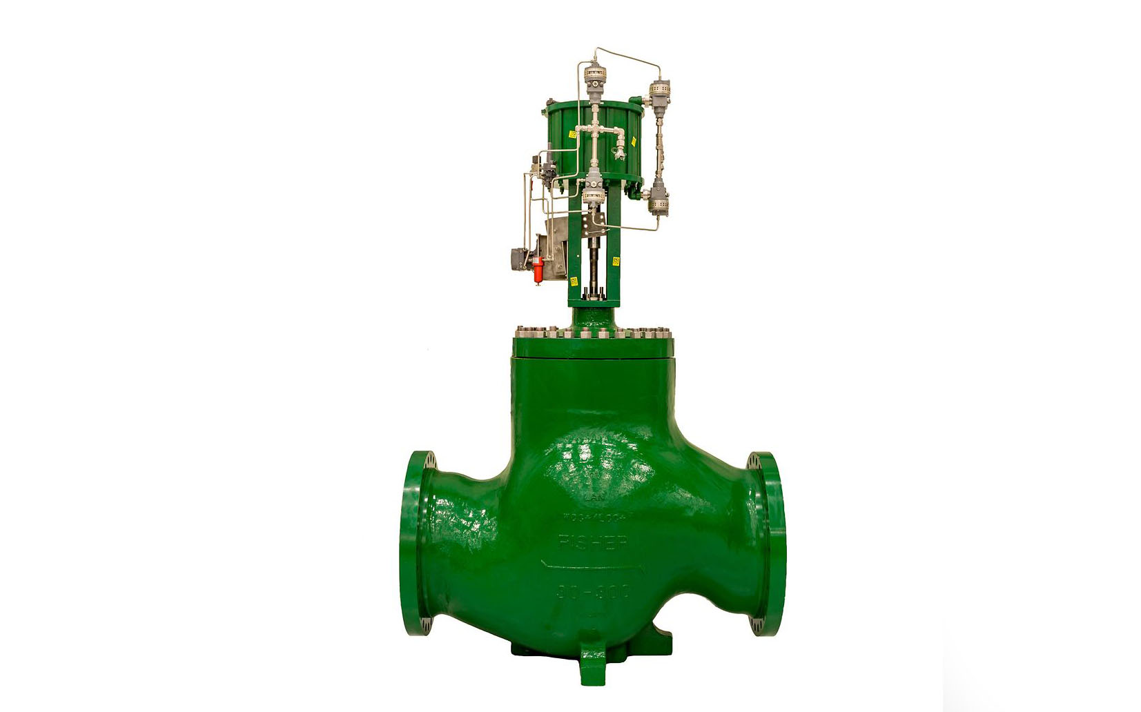
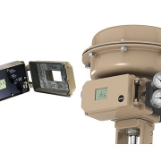
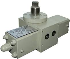
Type 3730-2 Electropneumatic Positioner
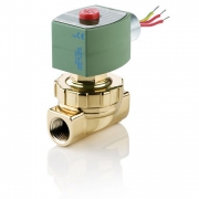
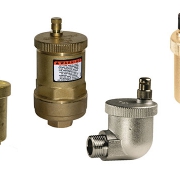
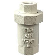
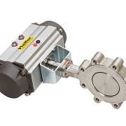
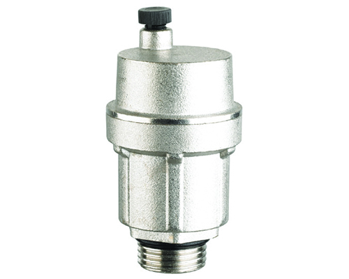
Application

  • Single-acting or double-acting positioner for attachment to pneumatic control valves. Self-calibrating, automatic adaptation to valve and actuator.

Setpoint

  • 4 to 20 mA

Valve travel

  • 3.6 to 300 mm

Opening angle

  • 24 to 100°

Special features

  • Simple attachment to all common linear and rotary actuators
  • Any desired mounting position of the positioner (but not suspended)
  • Simple single-knob, menu-driven operation
  • LCD easy to read in any mounted position due to the selectable reading direction
  • Configurable with a PC over the SSP interface using the TROVIS-VIEW software
  • Variable, automatic start-up with four different initialization modes
  • Preset parameters – only values deviating from the standard need to be adjusted
  • Calibrated travel sensor without gears susceptible to wear
  • Sub initialization mode (substitution) allows the positioner to be started up in case of emergency whilst the plant is running without the valve moving through the whole travel range.
  • Permanent storage of all parameters in EEPROM (protected against power failure)
  • A two-wire system with a small electrical load between 300 and 350 Ω depending on version Adjustable output pressure limitation
  • Activatable tight-closing function
  • Continuous monitoring of zero point
  • Integrated temperature sensor and operating hours counter
  • Two standard programmable position alarms
  • Self-diagnostics; alarms as condensed state conforming to NAMUR Recommendation NE 107, issued over a fault alarm contact or optional analog position transmitter
  • Integrated EXPERTplus diagnostics for control valves

Type 3730-3 Electropneumatic Positioner with HART communication

Application

  • Single-acting or double-acting positioner for attachment to pneumatic control valves. Self-calibrating, automatic adaptation to valve and actuator.

Setpoint

  • 4 to 20 mA

Valve travel

  • 3.6 to 300 mm

Opening angle

  • 24 to 100°

Special features

  • Simple attachment to all common linear and rotary actuators
  • Any desired mounting position of the positioner (but not suspended)
  • Simple single-knob, menu-driven operation
  • LCD easy to read in any mounted position due to the selectable reading direction
  • Configurable with a PC over the SSP interface using the TROVIS-VIEW software
  • Variable, automatic start-up with four different initialization modes
  • Preset parameters – only values deviating from the standard need to be adjusted
  • Calibrated travel sensor without gears susceptible to wear
  • Sub initialization mode (substitution) allows the positioner to be started up in case of emergency whilst the plant is running without the valve moving through the whole travel range.
  • Permanent storage of all parameters in EEPROM (protected against power failure)
  • A two-wire system with a small electrical load of 410 Ω
  • Adjustable output pressure limitation
  • Activatable tight-closing function
  • Continuous monitoring of zero point
  • Integrated temperature sensor and operating hours counter
  • Two standard programmable position alarms
  • Self-diagnostics; alarms as condensed state conforming to NAMUR Recommendation NE 107, issued over a fault alarm contact or optional analog position transmitter
  • Integrated EXPERTplus diagnostics for control valves

Type 3730-4 Electropneumatic Positioner with PROFIBUS-PA communication

Application

  • Positioners for attachment to pneumatic control valves

Valve travel

  • from 3.6 to 300 mm ·

Opening angle

  • 24 to 100°

Special features

  • PROFIBUS-PA Profile 3.01 certified positioner fulfilling all compulsory requirements of PROFIBUS-PA Profile 3.02
  • Automatic ID adaptation according to PROFIBUS-PA Profile 3.02 to facilitate the replacement of positioners with Profile 2.0 or 3.0 (e.g. Type 3785)
  • Classified status alarms acc. to NAMUR Recommendation NE 107
  • DTM file available to integrate the positioner into FDT/ DTM in compliance with specification 1.2
  • Simple attachment to all common linear and rotary actuators
  • Any desired mounting position of the positioner (but not suspended)
  • Single-knob, menu-driven operation
  • Automatic start-up
  • LCD easy to read in any mounted position due to the selectable reading direction
  • Integrated EXPERTplus diagnostics for control valves
  • Online changing of control parameters
  • Automatic zero monitoring
  • Calibrated travel sensor without gears susceptible to wear
  • Permanent storage of all parameters (protected against power failure)
  • Negligible influence of temperature and supply air
  • Adjustable output pressure limitation
  • Activatable tight-closing function
  • Binary input for DC voltage signals
Solenoid Valves ASCO

General Service Solenoid Valves ASCO

General Service Solenoid Valves ASCO series 8210

ASCO solenoid valves control the critical flow of air, gas, water, oil, and steam in applications spanning numerous industries. ASCO’s RedHat power management technology sets a new industry standard for reliability and power consumption, accepting both AC and DC voltages while improving performance.

These 2-way, 3-way, and 4-way solenoid valves can handle most fluid control applications and are now available with Class I, Division 2 approvals

ASCO General Service Valves

ASCO general service valves control the flow of neutral gases. They are known for their long life and fast response time available in multiple mounting configurations.

The solenoid is an electromagnetic part of a valve, comprised of a coil, core tube, core, and enclosure. The ASCO RedHat brand offers the world’s largest selection of 2-way, 3-way, and 4-way solenoid valves, designed to handle the most demanding fluid control applications.

ASCO’s 2-Way solenoid valves have one inlet and one outlet and are used to permit and shut off fluid flow. The two types of operations are Normally Closed (NC) and Normally Open (NO). Two types of constructions apply to 2-way solenoid valves, which are direct acting and internally piloted.

With Direct acting constructions, the solenoid is energized, the core directly opens the orifice of a Normally Closed valve or closes the orifice in a Normally Open Valve. The valve will operate at pressures from 0 psi to its rated maximum.

Internally piloted constructions use line pressure to assist operation. When the coil is de-energized (on a Normally Closed Valve), the pilot orifice is closed and line pressure is applied to the top of the piston or diaphragm through the bleed orifice, closing the valve.

ASCO 3-Way Solenoid Valves have three pipe connections and two orifices. When one orifice is open, the other is closed and vice versa.

They are commonly used to alternately apply pressure to exhaust pressure from a valve actuator or a single acting cylinder. These valves can be normally closed, normally open or universal.

ASCO 4-Way Solenoid Valves have four or five pipe connections, commonly called ports. One pressure inlet, two cylinder ports providing pressure to the double acting cylinder or actuator and one or two outlets to exhaust pressure from the cylinders. They have three types of construction, single solenoid, dual solenoid or single air operator.

INDUSTRIES

  • Medical & Life Science
  • Oil & Gas
  • Other Industries
  • Water and Wastewater

APPLICATIONS

  • Analytical & Diagnostic Equipment
  • Automotive
  • Heating Equipment
  • Press Room & Metal Stamping

FEATURES

  • ​​​​​​​​​​​​​​​​​​​​​​​​​​​​​​​​​​​​​A wide range of pressure ratings, sizes, and resilient materials provide long service life and low internal leakage
  • Our most economical, high flow valves for liquid, corrosive, and air/inert gas service
  • Industrial applications include: car wash, air compressors, pumps, laundry equipment, industrial water control

Technical Features

Function

  • 2 way -2/2 Normally closed
  • 2 way -2/2 Normally open

Body Material

  • Brass
  • Stainless Steel

Media

  • Air, Inert Gas
  • Dry Air
  • Fuel Gas
  • Hot Water
  • Light oil
  • Natural Gas
  • Oxygen
  • Vacuum
  • Water

Pipe/Port Size

  • 1/4″
  • 3/8″
  • 1/2″
  • 3/4″
  • 1″
  • 1 1/2″
  • 1 1/4″

Port Type

  • NPT

Voltage

  • 110 to 240 AC/DC Ranging
  • 100-240 V
  • 110 AC
  • 110-120 AC-60
  • 115 AC
  • 12 DC
  • 12 to 24 DC Ranging
  • 12-24 DC
  • 120 AC
  • 125 DC Battery Charging
  • 125 DC
  • 12 DC
  • 208 AC
  • 220 AC
  • 24 AC
  • 24 DC
  • 24 to 120 AC/DC Ranging
  • 24-120
  • 240 AC
  • 24 DC
  • 440 AC
  • 480 AC

Frequency

  • 50
  • 50/60
  • 60

Flow Range (Cv)

  • 1 to 2
  • 2 to 4
  • 6 to 14
  • Over 14

Max Op. Press. Air Range(PSI)

  • Vacuum to 150
  • 150 to 500

Limit Switch

Limit Switch

A Limit Switch is an electrical contact that is closed (or opened in some cases) by a variety of mechanical attachments (rollers, “whiskers”, levers, etc.) typically used as an input to a control system (relays, PLCs, etc.) to indicate the presence or absence of a physical object. Non-contact sensors like optical or metallic proximity switches are also sometimes called limit switches.

Presence Sensing is the act of detecting the presence or absence of an object with a contact or non-contact sensing device. The sensors then produce an electrical output signal that can be used to control equipment or processes.

Mechanical limit switches are contacted sensing devices widely used for detecting the presence or position of objects in industrial applications. The term limit switch is derived from the operation of the device itself. As an object (or target) makes contact with the operator of the switch, it eventually moves the actuator to the “limit” where the electrical contacts change state.

Through this mechanical action, electrical contacts are either opened (in a normally closed circuit) or closed (in a normally open circuit). Inductive proximity, capacitive proximity, and photoelectric sensors perform this same process through non-contact sensing.

Limit Switches Application

A limit switch is an electro-mechanical device that consists of an actuator mechanically linked to a set of contacts. When an object comes into contact with the actuator, the device operates the contacts to make or break an electrical connection. Limit switches are used in a variety of applications and environments because of their ruggedness, simple visible operations, ease of installation and operational reliability.

Limit switches are used in an assortment of applications and environments due to their ruggedness, simplicity of installation and reliability of operation.

They are available in a variety of body, rotary arm styles, operation requirements, and environmental factors including moisture, contamination, temperature, shock, and vibration. Other factors to consider when selecting a limit switch include operating force, reset force, over-travel, pre-travel, along with safety requirements. Limit switches are also available in four unique categories: Global, Medium-duty, Heavy-duty, and Safety Locking an Unlocking Styles.

Some application of limit switches:

  • Material handling – packaging, moving, warehousing, distribution
  • Working where people cannot. Inside a sawmill, a high-speed saw quickly reduces logs into construction beams.
  • Food & beverage packaging, distribution
  • Fire safety
  • Manufacturing – automotive/heavy equipment, machining, marine/aviation, glass & plastics
  • Metals – mining, refining, processing, forming
  • Commercial applications
  • Control cabinets
  • Heavy Conveyors
  • Metal processing
  • Gates, Doors, Hinges
  • Control cabinet doors
  • Indoor & outdoor environments

Mechanical limit switch operators are available in many shapes and sizes based on their functionality and application. Switches can be divided into two types: momentary and maintained. Momentary, or “spring return” switches return to their normal state as soon as the actuator is released from the object it is sensing. Maintained switches will remain in the actuated position even after the actuator has been released.

Air Vent Valve

Air Vent Valve

Air Vent Valve

An Air Vent Valve is a safety device that discharges air at the water supply piping in order to avoid air related problems in the water piping systems.

The product line-up includes both air vents for use on pipelines for liquids and those for use on pipelines for steam.

The air vents for piping carrying liquids make use of Free Float steam trap technology for a tight seal and excellent durability.

There are two types of air vent series for piping carrying liquids. One features a specialized rapid initial air vent to discharge initial air when the supply of liquid begins, and the other features an automatic air vent to discharge air regularly during operation.

The air vents for steam piping make use of thermostatic steam trap technology to discharge not only cold initial air, but also hot air.

Application of Air Vent

  • The cold and hot water supply system
  • Hot water boiler
  • The solar hot water system
  • Other various devices
  • Air conditioning system
  • Hot water heater appliance
  • Pressure tank

Type of Air Vent

Rapid Air Vent

Air Vent

  • This type of air vent use where the discharge of large quantities of initial air is required. Once the valve closes, it remains closed even if air enters. Also, install an automatic air vent if it is necessary to discharge air during operation.

Applications

  • Water lifting pumps
  • fire-extinguishing equipment
  • water transport lines
  • water storage tanks
  • hot water tanks
  • holding tanks for liquids.
  • Water
  • hot water

Air VentAutomatic Air Vent

Automatic air vents are most suited for heating systems and other closed circuit hot water systems which require an efficient and automatic removal of air whilst the system fills with water.

A vacuum break is fitted onto the bottom of the valve in order to prevent an air lock forming and encourages air to be released from the water within the system.


Steam Air Vent

Balance-pressure type air vents are usually recommended for removing air in steam systems. Bimetal type air vents also exist, however, these are not recommended for removing hot air from steam systems because the valve opening temperature is more or less fixed. This is different from the valve on balanced pressure type air vents, which opens at a temperature that is a certain number of degrees lower than the saturation temperature of the steam. Hot air is therefore discharged at all times regardless of fluctuations in steam pressure.

Valve Manifold

Valve Manifold

Valve Manifold

The Valve Manifold used to protect the DP transmitter and pressure gauge from a higher range. This device isolates the transmitter from fluid pressure for calibration and for maintenance purposes.

The manifold is a combination of valves in a single body. Each valve will have separate openings ad controls. The manifolds commonly use the ball, bleed, needle, and vent valves.

3-valve manifold

The 3-valve manifold consists of two shut-off valves and one pressure compensating valve. The shut-off valves separate the process from the differential pressure measuring instrument. The pressure compensating valve enables the compensation between ⊕ side and ⊖ side to avoid one-sided overpressure during commissioning and operation.

5-valve manifold

Compared to the 3-valve manifold, the 5-valve manifolds equipped with two additional vent valves. One vent valve per pressure side allows operators the targeted venting of one or both pressure sides of the measuring arrangement.

Through the non-rotating spindle tip, the wear of the sealing elements is reduced. This results, particularly with frequent opening and closing, in a noticeable increase in the service life of the valve manifold.

Advantages of a manifold valve

Manifold valves are used in a number of different applications, ranging from mobile machinery to heavy industrial equipment.

When included in fluid control and/or regulation system, valve manifolds have shown to improve efficiency as well as reduce energy costs. Other advantages include:

  • Shorter path flows which reduces pressure drop and heat fluctuations, improving the overall energy efficiency of the system
  • Reduction in installation costs as well as fluid connections because of a simpler, more compact design
  • Minimum chances of oil leak due to less number of connections, further reducing the need for upkeep against fatigue, wear and  lose joints
  • Improved layout due to fewer hoses and connections
  • Small, compact cartridge sizes which suits confined spaces

Applications

  • Shut off and vent pressure measuring instruments
  • For gaseous and liquid aggressive media that are not highly viscous or crystallizing, also in aggressive environments
  • Process industry: Oil & gas, petrochemical, chemical industries, power generation, water, and wastewater


Valve Actuator

Types and structure of Valve Actuator

Types and structure of Valve Actuator

A Valve Actuator is a mechanical device that uses a power source to operate a valve. This power source can be electric, pneumatic (compressed air), or hydraulic (the flow of oil). There are two main types of actuators, one for each of the two main types of valves that require them.

Selection of the best actuator type for any application is dependent on many factors including:

  • Valve type
  • Power sources available
  • Environment of installation
  • Operational functions and characteristics
  • Cost

Types of Valve Operation

There are two primary types of valve actuators. Understanding how a valve operates is the first step in choosing the appropriate actuator.

  • Rotary Valve Actuators
    As the name implies, rotary valve actuators produce the rotational motion needed to operate roatary valves such as ball, plug, and butterfly valves. Rotary actuators are available in many different styles, each with its own benefits.
  • Linear Valve Actuators
    Linear valves such as a globe, gate, and pinch valves – due to their distinctly different operation – require actuators that are drastically different from the rotary type. These actuators must produce linear motion to operate the valve. They are also available in many styles.

Types of Valve Actuator

electric valve actuator
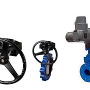
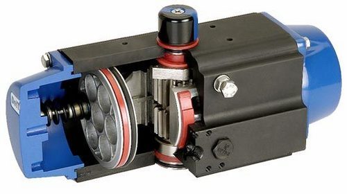
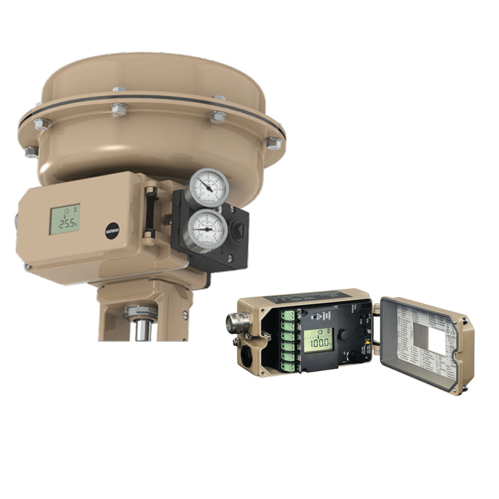
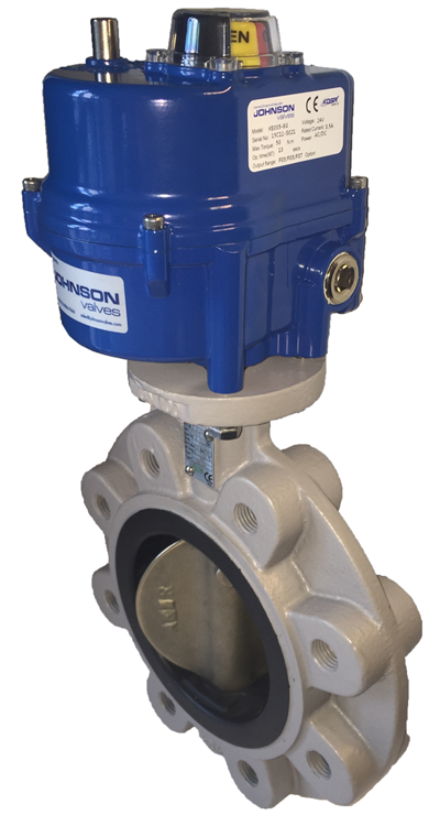
1-Electric Valves Actuators

This type of actuator is motor-driven or what the name implies is powered by electricity. They come in various designs and sizes to match different valve applications.

Depending on the design, the power will either be direct current (DC) or alternating current (AC). This electricity will supply the necessary torque to open or close the valve. Since electric actuators rely on electricity, it would fail to operate when there is a power outage.

This is a disadvantage especially at critical times when the valve is in the vital process of opening or closing and got interrupted. There are cases when valves are hard to turn because they are seldom used or handling sticky or abrasive materials. When this happens, the operators will have to specify electric actuators with extra torque so they can turn the valve with ease.

For added assurance that the valve will be controlled anytime it is needed to, it is recommended to attach manual control wheels or handles.

It can also prevent motors from burn out or overheat because of much energy exerted from turning sticking valves. In order to protect the motor, there are various ways that can be employed such as electric current limiting sensors, motor overheats or over-torque. No matter what the type and the design of actuators; overload protection should be attached on it to prevent malfunction due to a stuck valve.

2-Hydraulic Valves ActuatorsHydraulic valve actuator

In contrast to electric actuators that rely on electricity to work, hydraulic actuators move mechanisms through water pressure or other fluid. They are commonly used in butterfly valves since it does not require a large opening within the pipe to control the flow of fluid. This type of actuator is not recommended to use in places which temperature reaches below freezing as when the water solidified, it will stop providing hydraulic energy needed for the operation.


3-Pneumatic Valves Actuators

This device, on the other hand, takes energy from a change of air pressure to produce motion. There are various types of pneumatic valves actuators such as rotary actuators, single or double acting pneumatic cylinders and diaphragm actuators. They produce various motions that are capable of moving the valve in the required direction.

  • Manual actuators are the most common type of valve actuators. Manual actuators include handwheels attached to the valve stem directly and handwheels attached through gears to provide a mechanical advantage.
  • Electric motor actuators consist of reversible electric motors connected to the valve stem through a gear train that reduces rotational speed and increases torque.
  • Pneumatic actuators use air pressure on either one or both sides of a diaphragm to provide the force to position the valve.
  • Hydraulic actuators use a pressurized liquid on one or both sides of a piston to provide the force required to position the valve.
  • Solenoid actuators have a magnetic slug attached to the valve stem. The force to position the valve comes from the magnetic attraction between the slug on the valve stem and the coil of the electromagnet in the valve actuator.