Pressure gauges Snubbers

Pressure gauges Snubbers

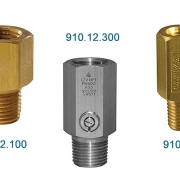
Pressure gauges Snubbers Model 910.12

Pressure gauge snubbers are intended to suppress the effect of pressure pulses and pressure peaks, which are common reasons for gauge failure. Porous snubbers incorporate a fixed mesh disk. Piston snubbers are supplied with five pistons for use with a variety of media. Adjustable pressure gauge snubbers are provided with an adjustable needle valve that enables the operator to restrict the flow as operating conditions may demand even when the snubber is in service.

Pressure gauge snubbers will considerably increase the service life of pressure gauges in harsh applications such as on reciprocating pumps and compressors, hydraulic presses or fluid power systems and will additionally improve the reading accuracy of the gauge.

pressure snubbers protect your pressure gauge or transducer from pressure spikes and surges and damaging pulsation. Snubbers extend the life of your pressure instruments because they protect the bourdon tube and movement from seeing harsh spikes and surges that could cause failure by rupturing the diaphragm of the transducer or the gauge bourdon tube or causing the movement teeth to skip or dislodge.

Snubbers reduce the day to day “wear and tear” on the instrument, lessening the need to replace. Units are available in both brass and 316 stainless steel, and in three different porosities for various pressure media including gas, liquid, and heavy oil.

Overpressure Protectors are triggered to protect your pressure instrument when the pressure exceeds the rated set pressure.  A spring-loaded piston triggers a valve to close when the pressure goes over the pressure range, protecting the instrument from a pressure surge or spike.  Once the pressure falls back to normal the spring will open the valve again.  All units are made of 316 SST for corrosive pressure media.  Three different part numbers are available, depending on your pressure requirements.

Snubbers Application

Snubbers are typically used in-line with a pressure gauge to suppress line pulsations and keep the gauge pointer steady.

Pressure gauge snubbers will substantially increase the life of a pressure gauge where there is pulsation in the line. i.e. for use on pumps, hydraulic presses or fluid power systems. They will also improve the reading accuracy of the gauge.

Technical Feature

Pressure Connection

  • ¼” NPT or ½ NPT male x female

 Body Material

  • Brass or stainless steel

Piston Material (Type 910.12.200)

  • Stainless steel

Needle Valve Material (Type 910.12.300)

  • Stainless steel

O-Ring Material (Type 910.12.300)

  • Brass: Buna-N
  • Stainless Steel: FPM (Viton)

Pressure Rating

  • Brass: 3000 psi – 5000 psi
  • Stainless Steel: 5000 psi – 15,000 psi

Temperature Rating

  • 14°F to 248°F (-10°C to 120°C)

Application/ Media

910.12.100 Porous Snubber

  • Air, steam, gas, Light oil, water

910.12.200 Piston Snubber

  • Use with various media per piston selection

910.12.300 Adjustable Snubber

  • Adjustable to various media types


Digital Probe Thermometer

Fluke 51 II Handheld Digital Probe Thermometer

Fluke 51 II Handheld Digital Probe Thermometer

In a short time, hand-held infrared (IR) thermometers have gone from exotic to commonplace. Portable and convenient, they are useful for troubleshooting and checking both product quality and process quality. Fluke’s family of IR thermometers offers users speed and convenience.

Applications for infrared thermometers

Infrared thermometry can be used for process monitoring, plant predictive and preventive maintenance, electrical applications, quality assurance, and other applications.

Infrared (IR) non-contact thermometers are ideal for moving targets and machinery, hazardous and inaccessible or distant targets, electrical components, “big picture” evaluations of machinery or surfaces, trending records, and even protection against litigation and insurance claims. In fact, insurance companies are encouraging their customers to implement preventive infrared scanning.

IR thermometers and imagers can save time and money for contractor and customer alike, as well as perform diagnostics that were previously impossible without shutting down systems.

  1. Electrical Maintenance
  2. Equipment Maintenance
  3. Building Controls
  4. HVAC/R
  5. Process/Product
  6. etc

The Fluke Model 51  Thermometer (“the thermometer”) are microprocessor-based, digital thermometers designed to use external J-, K-, T-, and E type thermocouples (temperature probes) as temperature sensors. Use the thermometer only as specified in this manual. Otherwise, the protection provided by the meter may be impaired.

The Fluke 51 II single input digital thermometer delivers fast response with laboratory accuracy (0.05% + 0.3°C). You can use the 51 II to measure contact temperature on motors, insulation, breakers, pipes, corroded connections, liquids, and wires with industrial standard J, K, T, or E-type thermocouple temperature sensors. The user friendly-front panel and large, backlit display make it easy to view results. And the sleep mode feature preserves battery life to give you a typical thousand hours of operation.

Other useful features:

  • Easy-to-access battery door that allows replacing the battery without breaking the calibration seal
  • Comes with splash- and dust-resistant case protected by an impact-absorbing holster and a three-year warranty
  • Powered by three, standard AA batteries -30-
  • Includes an electronic offset function that compensates for thermocouple errors to maximize overall accuracy
  • Handles temperatures up to 900°C (1600°F)
  • Provides a user-friendly front panel that is easy to set up and operate
  • Offers sleep mode to increase battery life; 1000-hour battery life typical
  • Offers optional ToolPak accessory to hang the thermometer from any metal object (with the rare earth magnet) or secure around a pipe (with hook-and-loop straps) for hands-free operation

Temperature accuracy

Above -100°C

  • J, K, T, E, and N-type: ±[0.05% + 0.3°C]
  • R and S-type: ±[0.05% + 0.4°C]

Below -100°C

  • J, K, E, and N-types: ±[0.20% + 0.3°C]
  • T-type: ±[0.50% + 0.3°C]

Temperature

J-type

  • -210°C to 1200°C

K-type

  • -200°C to 1372°C

T-type

  • -250°C to 400°C

E-type

  • -150°C to 1000°C

N-type

  • -200°C to 1300°C

R and S-type

  • 0°C to 1767°C

Temperature scale

  • ITS-90
Gas Actuated Thermometer WIKA model 73

Gas Actuated Thermometer WIKA model 73

Gas Actuated Thermometer WIKA model 73

Dial thermometers use a metal pointer on a circular scale to indicate temperature measurements. They have two main components: the needle and a temperature sensor.  The way a dial thermometer works depends on the type of thermometer it is. Options include bimetal, liquid or gas-filled and vapor-tension, they are described below.

The model 73 gas-actuated thermometer has been developed and is manufactured in accordance with the EN 13190 standard. The high-quality thermometer has been designed especially for the requirements of the process industry. Especially in the chemical and petrochemical, oil and gas, and power engineering industries, the thermometer completely manufactured from stainless steel is used successfully.

The stem, the process connection and the case of the gas-actuated thermometers are made from stainless steel. To allow optimum fitting to the process, individual insertion lengths and process connections are available. The thermometers have a high ingress protection of IP65 and can be used in outdoor applications even at negative temperatures. With liquid damping operation under high vibration, conditions are possible. Due to the wide variety of possible designs, the model 73 gas-actuated thermometers can be perfectly adapted to any process connection or location.

With the adjustable stem and dial version, the case can be adjusted precisely to the desired viewing angle. With the contact bulb version, temperature measurements are possible without any contact with the medium, even when the pipe diameter is extremely small. The contact bulb is intended for external mounting on pipes and tanks. When mounting this thermometer version, it must be ensured that the contact bulb is in contact with the measuring point over its complete length.

Applications of the gas-actuated thermometer

  • General process instrumentation in the chemical and petrochemical industries, oil and gas industries, energy and water/wastewater industries
  • Universally suitable for machine building, plant, tank, apparatus construction, and food industry
  • Temperature measurement without any contact with the medium
  • Mounting in instrument boards, control cabinets, control panels

Technical Data

Measuring principle

  • Gas-pressure inert gas filling, physiologically safe

Nominal size in mm

  • 100, 160

Connection designs

  • S                Standard (threaded connection)
  • 1                Plain stem (without thread)
  • 2                Male nut
  • 3                Union Nut
  • 4               Compression fitting (sliding on the stem)
  • 5               Union nut and loose threaded connection
  • 6               Compression fitting (can be adjusted on either capillary or spiral protective sleeve)
  • 7               Compression fitting at the case

Model

A73.100

  • Dial: 100mm, Back mount (axial)

A73.160

  • Dial: 160mm, Back mount (axial)

R73.100

  • Dial: 100mm, Lower mount (radial)

R73.160

  • Dial: 160mm, Lower mount (radial)

S73.100

  • Dial: 100mm, Back mount, adjustable stem, and dial

S73.160

  • Dial: 160mm, Back mount, adjustable stem, and dial

F73.100

  • Dial: 100mm, Version with capillary

F73.160

  • Dial: 160mm, Version with capillary

Accuracy class Class

  • 1 per EN 13190 at 23 °C ±10 °C ambient temperature

Material

Case, ring

  • Stainless steel 1.4301

Stem, process connection

  • Stainless steel 316SS

Adjustable stem and dial

  • version Stainless steel
  • swiveling 90°
  • rotatable 360°

Panel frame

  • Steel galvanized

Capillary

  • Ø 2 mm, stainless steel 1.4571, bending radius no less than 6 mm
  • Length to customer specification

Dial

  • Aluminium white, black lettering

Window

  • Laminated safety glass

Pointer

  • Aluminum, black, micro adjustment

Temperature limits for storage and transport

  • -50 … +70 °C without liquid damping
  • -40 … +70 °C with liquid damping

Permissible ambient temperature

  • -40 … +60 °C without/with liquid damping
Bourdon Tube Gauge WIKA Model 213.53

Bourdon Tube Gauge WIKA Model 213.53

Bourdon Tube Gauge WIKA Model 213.53

The Bourdon-tube gauge, invented about 1850, is still one of the most widely used instruments for measuring the pressure of liquids and gases of all kinds, including steam, water, and air up to pressures of 7,000 Bar.

The device (also shown in the figure) consists of a flattened circular tube coiled into a circular arc. One end is soldered to a central block and is open to the fluid whose pressure is to be measured; the other end is sealed and coupled to the pointer spindle.

When the pressure inside the tube is greater than the outside pressure, the tube tends to straighten, thus turning the pointer. The pressure is read on a circular scale.

Applications

  • For measuring points with high dynamic pressure loads or vibrations
  • For gaseous and liquid media that are not highly viscous or crystallizing and will not attack copper alloy parts
  • Hydraulics
  • Compressors, shipbuilding

Bourdon Tube Gauge WIKA Model 213.53

Technical Data

Design

  • EN 837-1

Bourdon tube pressure gauges, dimensions, metrology, requirements, and testing

Nominal size in mm

  • 50, 63, 100

Accuracy class

  • NS 50, 63: 1.6
  • NS 100: 1.0

Scale Ranges

  • NS 50: 0 … 1 to 0 … 400 bar
  • NS 63, 100: 0 … 0.6 to 0 … 1000 bar

or all other equivalent vacuum or combined pressure and vacuum ranges

Pressure limitation

NS 50, 63:

  • Steady: 3/4 x full-scale value
  • Fluctuating: 2/3 x full-scale value
  • Short time: Full-scale value

NS 100:

  • Steady: Full-scale value
  • Fluctuating: 0.9 x full-scale value
  • Short time: 1.3 x full-scale value

Permissible temperature

  • Ambient: -20 … +60 °C
  • Medium: +60 °C maximum

Temperature effect

When the temperature of the measuring system deviates from the reference temperature (+20 °C): Max. ±0.4 %/10 K of the span

Ingress protection

  • IP 65 per EN 60529 / lEC 529

Process connection

  • Cu-alloy, lower mount (LM) or back mount (BM),
  • NS 50, 63: G ¼ B (male), 14 mm flats
  • NS 100: G ½ B (male), 22 mm flats

Pressure element

NS 50, 63:

  • < 60 bar: Cu-alloy, C-type
  • ≥ 60 bar: Cu-alloy, helical type

NS 100:

  • < 100 bar: Cu-alloy, C-type
  • ≥ 100 bar: Stainless steel 316L, helical type

Movement

  • Cu-alloy

Dial

  • NS 50, 63: Plastic ABS, white, with pointer stop pin
  • NS 100: Aluminium, white, black lettering

Pointer

  • NS 50, 63: Plastic, black
  • NS 100: Aluminium, black

Window

  • Plastic, crystal-clear

Case

Natural finish stainless steel, with pressure relief at case circumference, 12 o’clock.

O-ring seal between case and connection. The scale ranges ≤ 0 … 16 bar with compensating valve to vent case.

Bezel ring Crimp ring, glossy finish stainless steel, triangular bezel

Filling liquid

  • Glycerine 99.7 %
Solenoid Valves ASCO

General Service Solenoid Valves ASCO

General Service Solenoid Valves ASCO series 8210

ASCO solenoid valves control the critical flow of air, gas, water, oil, and steam in applications spanning numerous industries. ASCO’s RedHat power management technology sets a new industry standard for reliability and power consumption, accepting both AC and DC voltages while improving performance.

These 2-way, 3-way, and 4-way solenoid valves can handle most fluid control applications and are now available with Class I, Division 2 approvals

ASCO General Service Valves

ASCO general service valves control the flow of neutral gases. They are known for their long life and fast response time available in multiple mounting configurations.

The solenoid is an electromagnetic part of a valve, comprised of a coil, core tube, core, and enclosure. The ASCO RedHat brand offers the world’s largest selection of 2-way, 3-way, and 4-way solenoid valves, designed to handle the most demanding fluid control applications.

ASCO’s 2-Way solenoid valves have one inlet and one outlet and are used to permit and shut off fluid flow. The two types of operations are Normally Closed (NC) and Normally Open (NO). Two types of constructions apply to 2-way solenoid valves, which are direct acting and internally piloted.

With Direct acting constructions, the solenoid is energized, the core directly opens the orifice of a Normally Closed valve or closes the orifice in a Normally Open Valve. The valve will operate at pressures from 0 psi to its rated maximum.

Internally piloted constructions use line pressure to assist operation. When the coil is de-energized (on a Normally Closed Valve), the pilot orifice is closed and line pressure is applied to the top of the piston or diaphragm through the bleed orifice, closing the valve.

ASCO 3-Way Solenoid Valves have three pipe connections and two orifices. When one orifice is open, the other is closed and vice versa.

They are commonly used to alternately apply pressure to exhaust pressure from a valve actuator or a single acting cylinder. These valves can be normally closed, normally open or universal.

ASCO 4-Way Solenoid Valves have four or five pipe connections, commonly called ports. One pressure inlet, two cylinder ports providing pressure to the double acting cylinder or actuator and one or two outlets to exhaust pressure from the cylinders. They have three types of construction, single solenoid, dual solenoid or single air operator.

INDUSTRIES

  • Medical & Life Science
  • Oil & Gas
  • Other Industries
  • Water and Wastewater

APPLICATIONS

  • Analytical & Diagnostic Equipment
  • Automotive
  • Heating Equipment
  • Press Room & Metal Stamping

FEATURES

  • ​​​​​​​​​​​​​​​​​​​​​​​​​​​​​​​​​​​​​A wide range of pressure ratings, sizes, and resilient materials provide long service life and low internal leakage
  • Our most economical, high flow valves for liquid, corrosive, and air/inert gas service
  • Industrial applications include: car wash, air compressors, pumps, laundry equipment, industrial water control

Technical Features

Function

  • 2 way -2/2 Normally closed
  • 2 way -2/2 Normally open

Body Material

  • Brass
  • Stainless Steel

Media

  • Air, Inert Gas
  • Dry Air
  • Fuel Gas
  • Hot Water
  • Light oil
  • Natural Gas
  • Oxygen
  • Vacuum
  • Water

Pipe/Port Size

  • 1/4″
  • 3/8″
  • 1/2″
  • 3/4″
  • 1″
  • 1 1/2″
  • 1 1/4″

Port Type

  • NPT

Voltage

  • 110 to 240 AC/DC Ranging
  • 100-240 V
  • 110 AC
  • 110-120 AC-60
  • 115 AC
  • 12 DC
  • 12 to 24 DC Ranging
  • 12-24 DC
  • 120 AC
  • 125 DC Battery Charging
  • 125 DC
  • 12 DC
  • 208 AC
  • 220 AC
  • 24 AC
  • 24 DC
  • 24 to 120 AC/DC Ranging
  • 24-120
  • 240 AC
  • 24 DC
  • 440 AC
  • 480 AC

Frequency

  • 50
  • 50/60
  • 60

Flow Range (Cv)

  • 1 to 2
  • 2 to 4
  • 6 to 14
  • Over 14

Max Op. Press. Air Range(PSI)

  • Vacuum to 150
  • 150 to 500

Digital Pressure Gauge WIKA

Digital Pressure Gauge WIKA model DG10

A Digital Pressure Gauge WIKA displays the acting pressure in an integrated digital display. WIKA offers digital pressure gauges for general industrial applications and also for use in the field of testing and calibration. The indicator cases of our digital pressure gauges are rotatable for easy viewing if required and thus always ensure good readability. In addition, and intrinsically safe versions and instruments with wireless interface versions are also available.

A digital display is ideal for precise and fast pressure readings. The WIKA DG-10 features a durable stainless steel housing and integral battery power supply making it suitable for a wide range of applications and industries.

The multi-function display features a bar graph with a drag pointer function and a MIN/MAX memory. The MIN/MAX memory feature permits later recall of the minimum and maximum pressure readings.

The DG-10 is available in two versions: standard (DG-10-S) and enhanced (DG-10-E). Both versions allow the user to easily switch between the most widely-accepted international measurement units including bar, psi and MPa.

Additional features of the enhanced version include a back-lit display for use in low light conditions and a housing that can be rotated for optimal viewing. Additional user-programmable functions of the DG-10-E include auto power-off, tare function, and password protection.

Robust, precise digital indicator

The robust stainless steel case and battery power enable a flexible operation in various applications and industries. For a precise and quick on-site reading of a pressure value, a digital indicator is an ideal solution. The bar graph display and drag pointer function integrated into the display, as well as retrievable Min/Max peak values, enable effective analysis of the measuring point.

Customized installation

Through its rotatable case, the model DG-10-E can be easily adapted to local conditions. The backlighting also provides easy readability of the display in poor lighting conditions. Additional programming functions are Automatic power-off, tare function and password protection. There is unit switching between the units bar, psi and MPa already integrated into the standard model DG-10-S.

Proven sensor technology

For decades, sensors manufactured by WIKA have guaranteed high accuracy, long-term stability and repeatability in industrial pressure measurement

Applications of the digital pressure gauge

  • Oil and gas industry
  • Maintenance and service facilities
  • Calibration service companies and service industry
  • Simple calibrations directly on site

Measuring range

Gauge Pressure (Bar)

  • 0…5  / 0…10 / 0…20 / 0…50 / 0…100 / 0…160 / 0…200 / 0…250 / 0…400 / 0…600

Vacuum and +/- measuring ranges (Bar)

  •  -1…+5  / -1…+10

Hardware functions

Rotatability of the display

The display of the model DG-10-E can be rotated through 300°, thus it can be read from almost any position. Therefore the model DG-10-E can also be used in situations where mounting is difficult.

Backlighting

The model DG-10-E features backlighting so that the display can be easily read, even under poor lighting conditions.

Process connection

  • G1/2B , G1/4B , 1/2NPT, 1/4NPT, G1B flush, G1/2B flush

Display

  • 7-segment LCD

Pressure units

  • Standard: psi, bar
  • Selectable to: mbar, kg/cm², Pa, hPa, kPa, Mpa, mmH2O, mH2O, inH2O, inH2O (4 °C), inH2O (20 °C), inH2O (60 °F), ftH2O, mmHg, cmHg, inHg, inHg (0 °C), inHg (60 °F), kp/cm2, lbf/ft2, kN/m2, atm, Torr, micron as well as user-defined units

Memory

  • Standard: Min./Max.

Menu functions

  • Min. / Max. alarm (visual), power-off function, measuring rate, mean value filter, pressure rate, mean value (via adjustable interval), level indicator, Tare offset, display damping

Material

1- Wetted parts

  • Process connection: Stainless steel 316Ti
  • Sealing material: Stainless steel 316Ti
  • Sensor element: PH grade steel

2- Non-wetted parts

  • Case: Stainless steel 304
  • Front foil and membrane: Polyester

Power supply

  • The voltage supply is provided via two 1.5 V AA cells

Accuracy at reference conditions

  • ≤ ±0.5 % of span ± 1 digit


Remote Mount Industrial Thermocouple Model TC15

Remote Mount Industrial Thermocouple Model TC15

Thermocouples generate a voltage directly dependent on temperature. They are particularly suited for high temperatures up to 1,700 °C (3,092 °F).

Instrument designs from mineral-insulated sheathed cable are very resistant against extremely high vibration loads (depending on instrument model, the sensor element and wetted materials). For WIKA thermocouples, the accuracy classes standard and special limits (ASTM E230) or classes 1 and 2 (IEC 60581) are available.

TC15 series thermocouples are remote mounted industrial assemblies supplied with or without a temperature transmitter.

They are designed for applications where direct mounting is inaccessible, where there is excessive radiated or conducted heat, or applications where high vibrations exist.

An extensive range of elements, connection heads, insertion lengths, and process connections can be individually selected for the appropriate application.

Replacement sensors can also be configured for this model. Thermocouples in this series can be inserted directly into a process, or combined with a variety of thermowell designs.

Special Features

  • The sensor can be mounted into a thermowell or directly into a process with the use of a spring-loaded or compression process fitting.
  • The assembly can be supplied with or without a transmitter. Transmitters convert the millivolt input from the thermocouple to a linear analog or digital output (commonly 4-20 mA). This signal reduces potential inaccuracies in the circuit and negates the requirement for thermocouple extension wire.
  • The assembly has electrical approvals for explosion proof hazardous locations, ingress protection, and general purpose areas.
  • The thermocouple sensors available for this assembly are provided with a variety of sheath materials including austenitic 300 series and ferritic 400 series stainless steel, corrosion resistant and high-temperature oxidation resistant alloys.
  • Thermocouple diameters range from 0.063 inches to 0.250 inches and 1.5 mm. to 6 mm. Standard diameters are 0.125 inch & 0.250 inch and 6 mm.
  • For applications that are exposed to outside weather conditions or where moisture is present, the flexible armor extension can be provided with a moisture-proof jacket of PTFE or PVC.


Applications

TC15 series assemblies are suitable for most industrial and commercial applications including:

  • Chemical and petrochemical industries
  • Energy and power plant technology
  • Furnaces, kilns, ovens, and boilers
  • Incinerators
  • Machinery, plant and tank measurement
  • Oil and gas industries
  • Offshore exploration and drilling
  • Pipeline control
  • Power and utilities
  • Pulp and paper
  • Water and wastewater treatment

Technical Feature

Sensor Element:

  • K (NiCr-Ni)
  • J (Fe-CuNi),
  • E (NiCr-CuNi)
  • N (NiCrSi-NiSi)
  • T (Cu-CuNi)

Temperature range:

  • -200 °C to +1260 °C (depending upon element)

The number of sensors:

  • 2-wire single circuit
  • 4-wire dual circuit

Classification tolerance:

  • Class 2 and class 1 per DIN EN 60584
  • ISA standard and special to ANSI MC96.1-1982

Measuring point:

  • Ungrounded or grounded

Electrical approvals:

  • CSA, FM