
Butterfly Valve Advantages and Disadvantages
Butterfly Valve Advantages and Disadvantages
A Butterfly Valve is a shut-off valve with a relatively simple construction. In a closed position, the disc blocks the valve bore while in an open position, the disc turn allows flow. A quarter turn takes the valve from fully open to a fully closed position or the opposite, and thus the butterfly valve allows for quick opening and closure.
Butterfly valves can be used for a broad range of applications within water supply, wastewater treatment, fire protection, and gas supply, in the chemical and oil industries, in fuel handling systems, power generation etc. Some of the advantages for this type of valve are the simple construction not taking up too much space, and the lightweight and lower cost compared to other valve designs.
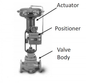
The valves can be operated by handles, gears or actuators according to any specific need.
Types of Butterfly Valves
Butterfly valves have been around for a long time, and are used for a variety of applications. They made their first appearance during the 1930s, and have been utilized by several industries ever since.
Often made out of cast iron, butterfly valve’s name is based on the functionality of its disc. There are a few different types of butterfly valves, however, they fall into two basic types – Lug and Wafer valves.
LUG BUTTERFLY VALVE
The lug version of the butterfly valve’s design is similar to a 3-piece ball valve in that one end of the line can be taken off without having an effect on the opposing side. This can be executed by using threaded inserts, flanges, along with two sets of lugs (bolts) that don’t utilize nuts since each flange features its own bolts. It’s also important to note that you don’t need to shut down the entire system in order to clean, inspect, repair, or replace a lug butterfly valve (you would need to with a wafer butter valve).
WAFER BUTTERFLY VALVE
A wafer butterfly valve’s function is to retain a seal to protect against dual-directional pressure differential in the flow of fluid. In other words, the wafer version of butterfly valves was designed to hold a tight seal, safeguarding against bi-directional pressure differential in order to avoid any backflow in systems that have been manufactured for uni-directional flow.
This is accomplished by using a tightly fitted seal, such as an O-ring, gasket, precision machined, along with a flat valve face on the downstream and upstream sections of the valve.
Both lug and wafer butterfly valves are used in a number of applications for industrial sectors that include food processing, pharmaceutical, chemical, oil, water as well as wastewater management.
Butterfly valves, for the most part, have replaced ball valves in a lot of industries. This is especially the case for those dealing with petroleum because they are less expensive and easy to install. It’s important to note that pipelines that contain butterfly valves can’t be ‘pigged’ for cleaning. “Pigging” is the process of making use of devices referred to as “pigs” to carry out a variety of maintenance operations.
BUTTERFLY VALVE APPLICATIONS
- Cooling water, air, gases, fire protection.
• Slurry and similar services.
• Vacuum service.
• High-pressure and high-temperature water and steam services.
• Compressed air or gas applications.
Advantages of a Butterfly Valve
- The compact design requires considerably less space, compared to gate, globe, or other valves.
- Light in weight.
- Quick acting; as a quarter-turn valve, it requires less time to open or close.
- Butterfly Valve is available in large sizes, ranging from NPS 1¹⁄₂ (DN 40) to over NPS 200 (DN 5000).
- They have low-pressure drop and high-pressure recovery.
- Provide bubble-tight service.
Disadvantages of a Butterfly Valve
- Butterfly Valve Throttling service limited to low differential pressure.
- Cavitation and choked flow are two potential concerns.
- Butterfly Valve disc movement guides and affects by flow turbulence
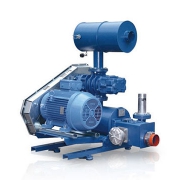
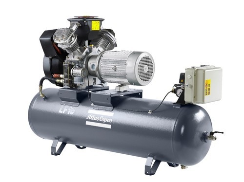 Piston Compressors
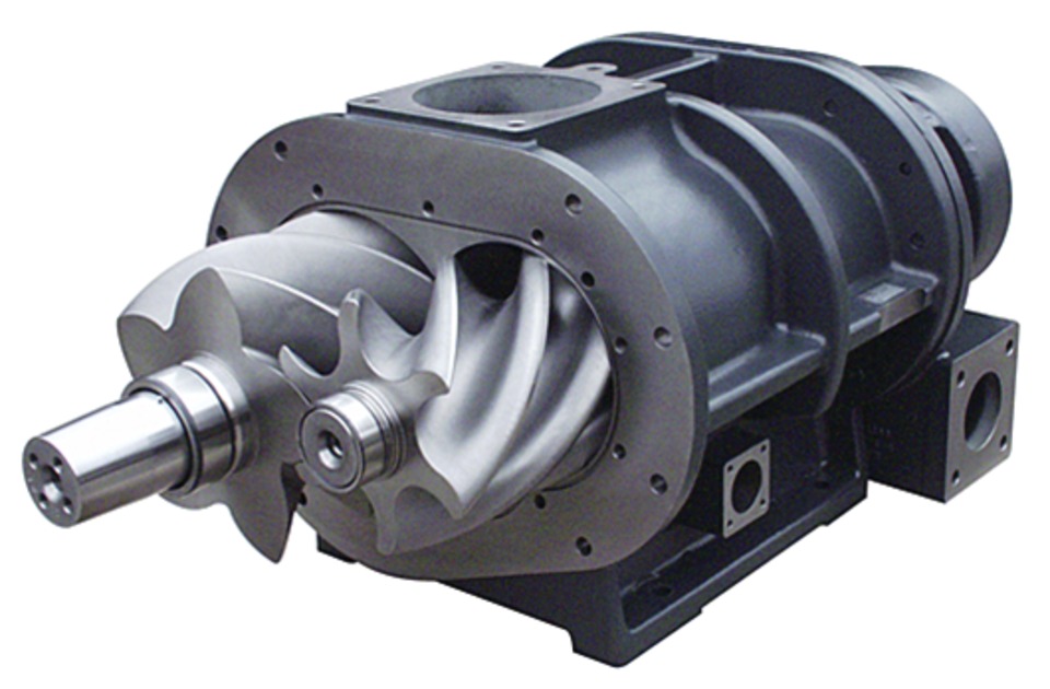 Rotary Screw Compressors
 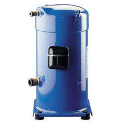 Scroll Compressors
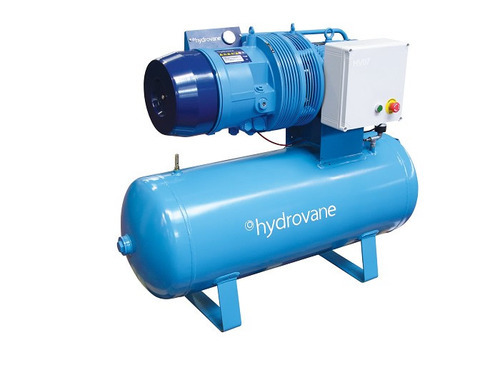
 Roots Blowers