Pressure Gauge Ashcroft
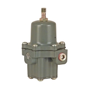
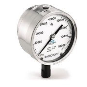
1109 Process Pressure Gauge Ashcroft
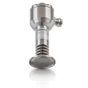
A pressure gauge is a mechanical instrument designed to measure the internal pressure and/or vacuum of a vessel or system. Trerice Pressure Gauges are offered in a variety of styles, sizes, and wetted part materials to meet the demands of standard and special applications.
Most Trerice Pressure Gauges are constructed with a bourdon tube sensing element. When the sensing element is subjected to pressure, it flexes and the resulting motion is transmitted as a measurement through a mechanical movement to the dial face pointer
The Ashcroft 1109 pressure gauge is a rugged instrument and an ideal choice when an ASME gauge with a solid front stainless steel case is a requirement. This model combines elements of reliability, performance, and safety. An ideal product that serves extremely well on challenging installation points.
FEATURES of Pressure Gauge Ashcroft
- PLUS!™ Performance dampens vibration, shock and pulsation effects
- Solid front design with full blowout back
- Epoxy coated system offers superior corrosion resistance
- Rugged design
TYPICAL USES
- Oil and Gas
- Offshore Oil Rigs
- Chemical and Petrochemical Plants
- Refineries
- Waterblasting / Water Jetting Equipment
- Specialized OEM Equipment
SPECIFICATIONS
Accuracy
- ±0.5% of span (ASME B40.100, Grade 2A)
Size
- 100mm
- 160mm
Ranges
- Vacuum, Compound 15 to 100,000 psi
Process Connection Location
- Lower
Process Connection Size
- 1 ⁄4NPT Male
- 1 ⁄2 NPT Male
- 1 ⁄4 High-pressure tubbing
Case Style
- Solid front with pressure relief back
Movement
- Adjustable
Window Material
- Glass (STD.)
- Safety glass (STD.)
- Shatterproof glass (OPT.)
Dial
- White aluminum with black markings
Pointer
- Aluminum
Weather Protection
- IP64
- IP65 Hermetically sealed
Dampening Options
- PLUS! ™ Performance, throttle screw, dampeners, capillary, diaphragm seals and snubbers
Mounting
- Stem
Approvals
- CRN
Bourdon Tube
- 316L SS
- Inconel for ranges greater than 40,000 psi
Process Connection
- 316 SS
Joints
- Welded
Case
- 304 SS
Ring
- Cam Lock 300 SS
Back Cover
- 304 SS
Datasheet
![]()