Float Switches Model WFS

Float Switches Model WFS

Float Switches are used for the point-based limit level detection of one or several levels. They work independently of foaming, conductivity, dielectric, pressure, vacuum, temperature, vapors, condensation, bubble formation, boiling effects, and vibrations and are suitable for almost all liquid media. The switching operation is free from wear and needs no power supply.

The simple and proven functional principle of the float switches enables a very wide range of applications, from general industrial applications through to use in process plants.

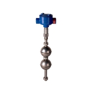
The Float Switches is comprised of a permanent magnet to ensure it moves along with the liquid level on a guide tube and provides accurate level readings. The guide tube is fitted with a reed contact (inert gas contact) and is energized by the approach of the float magnet.

By using a magnet and reed contact, the operation of the float switch is non-contact, free from wear and needs no power supply. The contacts are potential-free. Magnetic float switches are also available with multiple switch points.

The switch functions always refer to a rising liquid level: SPDT or change-over contact.

Using a float for two switch points creates a bi-stable switch operation, meaning that the switching status remains available when the filling level continues to rise above or drop below the switch point.

float switch is simple to mount and maintenance-free, providing a cost-effective solution.

Applications for a float switch

  • Level measurement for almost all liquid media
  • Pump/level control and monitoring for defined filling levels
  • Chemical industry, petrochemical industry, natural gas, offshore, shipbuilding, machine building, power generating equipment, power stations
  • Process water and drinking water treatment, food, and beverage industry

Connections

  • 6-1” ANSI / 150-600# RF flange
  • 2 – 1/2” MNPT
  • 60s-10s tri-clamp

Housing

  • Polyester NEMA 4x
  • Epoxy coated aluminum NEMA 4x or 7/9
  • Stainless steel NEMA 7/9

Features

  • Large range of application due to the simple, proven functional principle
  • For harsh operating conditions, long service life
  • Operating limits: -Operating temperature: T = -196…+350°C -Operating pressure: P = Vacuum to 40 bar -Limit density: ρ ≥ 300 kg/m³
  • Wide variety of different electrical connections, process connections, and materials.
  • FM approved version / NEMA 4x or 7/9 housing
  • Process connection, guide tube and float from 316L/316Ti stainless steel or plastic
  • Universal signal processing: connection direct to a PLC is possible, NAMUR connection, signal amplification/contact protection relays
  • Works independently of foaming, conductivity, dielectricity, pressure, vacuum, temperature, steam, condensation, bubble formation, boiling effects, and vibrations.

Data Sheet

ARMATUREN Butterfly Valve

ARMATUREN Butterfly Valve

ARMATUREN Butterfly Valve

A butterfly valve is a shut-off valve with a relatively simple construction. In the closed position, the disc blocks the valve bore while in open position, the disc is turned to allow flow. A quarter turn takes the valve from fully open to the fully closed position or the opposite, and thus the butterfly valve allows for quick opening and closure.

Butterfly valves are among the family of quarter-turn valves and work very similar to ball valves. The “butterfly” is a disk connected to a rod. It closes when the rod rotates the disc by a quarter turn to a position perpendicular to the flow direction. When the valve opens, the disk is rotated back to allow the flow.

Butterfly valves are used for on-off or modulating services and are popular due to their lightweight, small installation footprint, lower costs, quick operation and availability in very large sizes. These valves can be operated by handles, gears or automatic actuators.

Butterfly Valve Applications

Butterfly valves can be used across a wide range of applications. They perform well in large volume water applications and slurry applications. The following are some typical applications of Butterfly valves:

  • Cooling water, air, gases, fire protection, etc.
  • Slurry and similar services
  • Vacuum service
  • High-pressure and high-temperature water and steam services
  • Compressed Air or Gas Applications

Advantages of Butterfly Valves

1. The compact design requires considerably less space, compared to the gate, globe, or other valves.
2. Light in weight.
3. Quick-acting
4. low-pressure drop and high-pressure recovery
5. Provide a bubble-tight service.

Disadvantages of a Butterfly Valve

1. Throttling service is limited to low differential pressure
2. The disc movement is unguided and affected by flow turbulence.

Features

  • Soft Sealing
  • Maintenance-free
  • Good flow characteristic due to excellent Zeta-values
  • Seat material EPDM / NBR / FPM
  • Double sealing of the stem
  • Stainless steel disc
  • Centrical disc bearing
  • Nodular iron body

Specification

Medium:

  • Coldwater
  • warm water
  • process water

Pressure

  • PN16

Size

  • DN10
  • DN25
  • DN32
  • DN40
  • DN50
  • DN65
  • DN80
  • DN100
  • DN125
  • DN150
  • DN200
  • DN250
  • DN300
  • DN350
  • DN400

Temperature

  • -10°C – 100°C

Type

  • Wafer
  • Lug

Data Sheet

Pneumatic system

Pneumatic system

Pneumatic system

A Pneumatic system is a system that uses compressed air to transmit and control energy. Pneumatic systems are used in controlling train doors, automatic production lines, mechanical clamps, etc.

Compressed air pneumatic systems require methods of safe and precise control of the actuators unique to their accouterment. Although the medium is fluid, just as hydraulic or process water systems, the execution of control is different in many ways than with a liquid. What is shared in the conduction of any fluid power medium is the need for valves to control force, velocity, and direction of movement.

Application of Pneumatic Valve

1-Air preparation

Pressure relief valves will control pressure at their inlet port by exhausting pressure to atmosphere. Relief valves are typically used only in receivers or air storage devices, such as accumulators, as a means to prevent excessive pressurization. As such, relief valves are often called safety valves and are not typically appropriate for use anywhere but the air preparation stage.

Pressure regulators in pneumatic systems limit pressure downstream of the unit by blocking pressure upstream at the inlet. Regulators are used in the air preparation stage, as well as in control of cylinders and motors. The letter R in the acronym FRL stands for the regulator, which is installed downstream of the receiver tank, but before the circuit, they are regulating pressure for.

2-Flow controls

Flow controls Also common in pneumatic systems are valves to control flow. There are fewer available types of flow valves compared to pressure or directional valves, but most circuits apply them to make for easy adjustment to the cylinder or motor velocity. Controlling velocity in pneumatic systems is more complex than in a hydraulic system because the pressure differential between the work ports of a cylinder plays a larger part.

Flow control valves for pneumatic systems are quite simple, usually available in two configurations used in two different ways. One configuration is merely a variable restriction, with a screw or knob adjustment to open and close a variable orifice, which is also often referred to as a needle or choke valve. The other type introduces a check valve, which allows free flow in one direction, and restriction in the opposing direction. For whatever reason, this valve has hijacked the name flow control all for itself.

Type of Pneumatic Valve

Two Way Valves

Two-way valves turn the air on and off in applications such as shop air, branch airlines, supply pressure to systems, and supply air to tools, motors, and similar equipment. Two-way valves can also be used as vent valves.

Three-way Valves

Three-way valves are the same as 2-way valves with the addition of a third port for exhausting downstream air. Three-way valves are available in normally open or normally closed operating configurations. These valves are used to control single acting or spring return cylinders and any load which must be pressurized and alternately exhausted. These valves can also pilot other air operated valves.

Four-Way Valves

Four-way valves use two 3-way valve functions operated at the same time, one normally closed and one normally open. These valves have two outlet ports that alternate between being pressurized and exhausted. Four-way valves are used to operate double acting air cylinders, control bi-directional air motors and in air circuitry. Also, two single-acting cylinders can be operated with one 4-way valve.

The advantages of pneumatic systems

  • High effectiveness
  • High durability and reliability
  • Simple design
  • High adaptability to the harsh environment
  • Safety
  • Easy selection of speed and pressure
  • Environmental friendly
  • Economical

The disadvantages of pneumatic systems

  • Relatively low accuracy
  • Low loading
  • The processing required before use
  • Uneven moving speed
  • Noise
Differential pressure gauge WIKA

Differential pressure gauge WIKA

Differential pressure gauge WIKA Model 732.51

These differential pressure gauges are made of highly corrosion-resistant stainless steel and feature an all-metal, all-welded media chamber to ensure long-term leak tightness (no elastomer sealing elements).

A high overload safety is achieved by the all-metal construction and the close-fitting design of the pressure measuring diaphragm. With its high-grade stainless steel construction and robust design, this pressure gauge is geared to chemical and process engineering applications. It is suitable for gaseous or liquid media, also in aggressive ambiance.

The optionally available low-temperature version allows the use for temperatures of down to -70 °C (-94 °F). The scale ranges of 0 … 16 mbar to 0 … 25 bar is available to meet the requirements of a wide variety of applications.

Applications

  • For gaseous and liquid aggressive media that are not highly viscous or crystallizing, also in the aggressive ambiance
  • Monitoring and control of pumps
  • Filter monitoring
  • Level measurement in closed tanks

Technical Specification

Nominal size

  • 100 mm
  • 160 mm

Ambient temperature:

  • -20 … +60 °C unfilled
  • -40 … +60 °C with silicone oil filling
  • -70 … +60 °C Low-temperature version

Ingress protection

  • IP54 per IEC/EN 60529 (with liquid filling IP65)

Material

1- Measuring chamber with process connection (wetted)

  • Stainless steel 1.4571, lower mount (LM), 2 x G ¼ female

2- Case

  • Stainless steel, with pressure relief

Window

  • Laminated safety glass

Scale Ranges

  • 0 … 16 to 0 … 40 mbar
  • 0 … 60 to 0 … 250 mbar
  • 0 … 400 mbar
  • 0 … 0.6 bar
  • 0 … 1 bar
  • 0 … 1.6 bar
  • 0 … 2.5 to 0 … 25 bar

Data Sheet

Electric Actuator SAMSON

Electric Actuator SAMSON Type 3374

Electric Actuator SAMSON Type 3374

The Electric Actuator SAMSON Type 3374 is designed for all industrial applications. This actuator is a linear motion device ideal for valve sizes ranging from micro-flow valves to 6″ globe control valves.

The thrust output of the actuator for both extending stem and the retracting stem is limited to a maximum depending on the exact model.

Application

  • Electric Actuator for Plant Engineering and HVAC
  • Desalination
  • Tire Vulcanization

Features

  • Compact and simple actuator design to fit perfectly with the compact and simple valve design
  • Easier to transmit power over longer distanced compared to pneumatic and hydraulic
  • Ideal for low ambient temperature applications
  • Motor switched off by torque-dependent limit switches to prevent overloading
  • Thrust up to 2.5 kN
  • Optionally with fail-safe action for the version with electric override

Three-step version

  • Power supply: – 230 V with 50/60 Hz – 24 V with 50/60 Hz
  • Synchronous motor with maintenance-free planetary gear
  • Additional electrical equipment: 1-Mechanical limit contacts 2-Resistance transmitters

Version with digital positioner

  • Power supply: – 85 to 264 V with 47 to 63 Hz – 24 V with 47 to 63 Hz and DC
  • Stepper motor with maintenance-free planetary gear
  • All function settings performed using a rotary pushbutton on the actuator
  • Backlit LCD
  • Additional electrical equipment:1- Mechanical/electronic limit contacts 2- RS-485 module for Modbus-RTU communication
  • Settings performed in TROVIS-VIEW

Special version with the three-key operation

  • The actuator is not operated using the rotary pushbutton. Instead, keys on the cover are used for the operation.
  • This actuator version can be operated without having to remove the housing cover.

Principle of operation

The electric actuator consists of a reversible motor and a maintenance-free planetary gear with a ball screw drive. The motor is switched off by torque-dependent limit contacts or in case of overload.

What is the Actuator?

An actuator is something that converts energy into motion. It also can be used to apply a force. An actuator typically is a mechanical device that takes energy — usually energy that is created by air, electricity or liquid — and converts it into some kind of motion. That motion can be in virtually any form, such as blocking, clamping or ejecting. Actuators typically are used in manufacturing or industrial applications and might be used in devices such as motors, pumps, switches, and valves.

for more information about Types and structure of Valve Actuator click here.

datasheet