Safety Valve

Safety Valve

Safety Valve

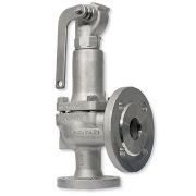
Safety valve is a valve that acts as a protection of equipment from exploding or damaging and it is mainly installed in pressure vessels such as chemical plants, electric power boilers, and gas storage tanks.
Safety Valve is a type of valve that automatically actuates when the pressure of inlet side of the valve increases to a predetermined pressure, to open the valve disc and discharge the fluid (steam or gas); and when the pressure decreases to the prescribed value, to close the valve disc again. Safety valve is so-called a final safety device which controls the pressure and discharges a certain amount of fluid by itself without any electric power support.
Safety valve support not only the safety of the energy industry but also the safety and security of our life.

Start to Discharge Pressure

The inlet pressure at which the safety valve actually starts to discharge and outflow of an extremely small quantity of fluid (steam or gas) are detected at the outlet. The extremely small quantity means a minimum amount of visually or audibly detectable steam, or a minimum amount of gas that can be detected audibly or by using a soap solution. The outflow does not mean the leakage from the valve seat.

Opening Pressure

The inlet pressure at which the valve disc “Pops.” The opening pressure is also called “popping pressure.” “Popping” is an action of discharging fluid inside the valve due to the sudden rise of the valve disc.

Set Pressure

The opening pressure or start to discharge pressure determined in designing.

Closing Pressure

The inlet pressure fell down to the level at which the valve disc and the valve seat are in contact and the lift becomes zero. It is also called “reseating pressure.”

Blowdown

The difference between opening pressure or start to discharge pressure and closing pressure

Over Pressure

The increasing pressure exceeds the set pressure of the safety valve.

Allowable Over Pressure

The overpressure within the allowable range.

Coefficient of Discharge

The coefficient used to calculate the actual discharge capacity from the theoretical discharge capacity. The coefficient is the ratio between the two capacities, and it counts the frictional resistance.

Certified Derated Coefficient of Discharge

The coefficient of discharge to be applied to calculate the certified capacity.

Flow Rating Pressure

The inlet pressure is taken as the basis for determining the certified capacity of the safety valve, which is the sum of the set pressure and the allowable overpressure.

Back Pressure

The pressures existing at the outlet of the safety valve. There are two types as the following: (a) Accumulated back pressure: The pressure existing at the outlet of a safety valve caused by the resistance of the outlet side when the safety valve has been relieved. (b) Existing back pressure: The pressure which has already been superimposed at the outlet before the safety valve is relieved.

Theoretical Discharge Capacity

The discharge capacity calculated supposing that the fluid is free from friction and its flow rate coefficient is 1, and that the valve discharges the ideal gas of fixed specific heat with isentropic change.

Lift

The amount of travel, in the axial direction of the valve or valve rod, away from the closed position to the opened position during discharge of the safety valve

Safety valves protect steam systems and tanks from excess pressure. As they are often the last link in the safety chain, they must remain operational in all conditions.
Safety valves discharge water vapor, neutral gas, steam, and fluid in the event of excess pressure. As soon as normal operating conditions are restored, they close and do not release any more medium.

Feature

Full bore type

  • Flanged
  • Cast Iron
  • Closed type

Application

  • Steam
  • Air
  • Other non-dangerous fluids

Working pressure

  • 0.045 – 1.6 MPa (20-100A) , 0.045 – 1.25 MPa (125A) , 0.045 – 1.0 MPa (150A) , According to PT rating

Max Temperature

  • 250 degree C

Body

  • Cast Iron

Spring chamber

  • Ductile Cast Iron

Valve

  • Stainless steel

Valve seat

  • Stainless steel
WAFER STYLE BUTTERFLY VALVE

HIGH PERFORMANCE WAFER STYLE BUTTERFLY VALVE SAMSON

HIGH-PERFORMANCE WAFER STYLE BUTTERFLY VALVE

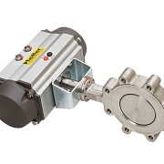
A butterfly valve is a shut-off valve with a relatively simple construction. In the closed position, the disc blocks the valve bore while in open position, the disc is turned to allow flow. A quarter turn takes the valve from fully open to the fully closed position or the opposite, and thus the butterfly valve allows for quick opening and closure.

Butterfly valves can be used for a broad range of applications within water supply, wastewater treatment, fire protection, and gas supply, in the chemical and oil industries, in fuel handling systems, power generation, etc. Some of the advantages of this type of valve are the simple construction not taking up too much space, and the lightweight and lower cost compared to other valve designs.

The valves can be operated by handles, gears or actuators according to any specific need.

The Pfeiffer BR14a double eccentric control butterfly valve is designed for general service applications up to the limits of the ANSI 150 pressure class rating. These general service applications include process events such as erosion, abrasion, and corrosion.

The Pfeiffer BR14a design increases flow capacities but also reduces the pressure recovery factor making the design more susceptible to cavitation, flashing, and flow noise generation. The double eccentric design of this butterfly valve will reduce the breakaway torques required from the actuator.

The Pfeiffer BR14a control butterfly valve has standard options such as low and high-temperature version. The Pfeiffer BR14a and BR14b can be assembled with a pneumatic, electric, hydraulic, or electro-hydraulic actuator. These control valves are designed according to the modular assembly principle, can be equipped with SAMSON GROUP actuators and valve accessories such as positioners, limit switches, and solenoid valves.

Technical Specification

Size

  • 3″ to 20″

ANSI Class

  • 150

Std. Materials

  • Carbon Steel, Stainless Steel

Temperature Range

  • 14 to 392oF (-10 to 200oC)

FEATURES & BENEFITS

  • Minimum material required compared to similar sized control valves of different types
  • The pneumatically actuated valve can be stroked extremely quickly
  • Double Eccentric disk design provides a tight seal, reduced breakaway torque and wear
  • Anti-blowout valve shaft design to increase reliability
  • Extended valve neck to allow easy installation in insulated pipelines
  • Soft seat rings can be replaced with metal seat rings on site
  • Throttling service rangeability is 50:1

Applications

  • Food & Beverage
  • Water & Wastewater
  • Iron & Steel
  • Chemical & Petrochemical

Data Sheet

Parker Solenoid Valve

Parker Solenoid Valve

Parker Solenoid Valve

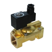
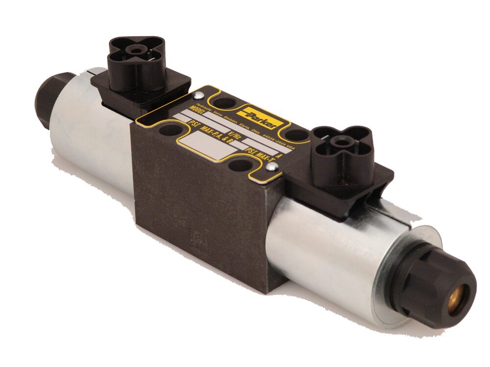
Parker Solenoid Valve is an electro-mechanical device that controls fluid flow. This is achieved by opening or closing one or several orifices in the solenoid valve. The (solenoid) coil is the electrical element that converts an electrical signal into a mechanical force which, in turn, shifts the mobile plunger that opens or closes an orifice (nozzle) by means of its seat disc(s). Solenoid valves are usually constructed from 3 distinct components:

  • the body (including the sleeve assembly)
  • the coil (or coil housing)
  • the housing (or nut/nameplate fixing elements)

These 3 modular components are in many cases interchangeable i.e. a valve body can be used with a number of coil/housing combinations.

1-Direct operated valves

The magnetic force is used directly to open or close the passage of fluid at the plunger sealing. The performance is limited by the available performance of the coil (limits of pressure/orifice size.) The pressure rating of the valve starts from zero bar to the maximum value.

2-Pilot operated valves

In cases where it is necessary to control higher flow/higher pressure, it is necessary to use pilot operated valves. The supply pressure enters the direct-operated “pilot stage” which directs the flow to a “pilot chamber” which, in turn, applies the pilot pressure over a large area (generally a diaphragm or a piston). Therefore, a large force is generated to move the main sealing elements against higher pressure or over a large orifice. One condition of operation is to have a minimum pressure available to shift the valve. In most applications, this presents no particular problems (refer to “Magnalift valves” below). The pressure rating of the valve starts from a minimum value (0.3 or 0.5 bar) up to the maximum value.

3-Magnalift valves

The magnalift valves combine the features of a direct operated and a pilot operated. A mechanical link between the plunger and the diaphragm retainer allows the valve to operate as a direct operated valve at low pressures and as a pilot operated valve at higher pressures. The advantage of this design is that the pressure rating of the valve starts from zero bar to the maximum value. Magnalift valves are specified when the valve controls the emptying/filling of a tank under gravity.

Parker Solenoid Valve Technical information

Actuation

  • Direct operated
  • Magnalift
  • Pilot operated

Body Material

  • Brass body
  • 303 Stainless steel body

Function

  • Normally closed
  • Normally open
  • Magnetic latch control

Connection

  • 1/8
  • 1/4
  • 3/8
  • 1/2
  • 1
  • 1 1/4
  • 1 1/2

Pressure (BAR)

  • 4 … 100 Bar

Data Sheet

Rosemount Temperature Transmitter

Rosemount Temperature Transmitter

Rosemount Temperature Transmitter

A temperature transmitter is an electrical instrument that interfaces a temperature gauge – such as a thermocouple, RTD, or thermistor – to a measurement or control device, such as a PLC, DCS, PC, loop controller, data logger, display or recorder.

Typically, temperature transmitters isolate, amplify, filter noise, linearize, and convert the input signal from the sensor then send (transmit) a standardized output signal to the control device. Common electrical output signals used in manufacturing plants are 4-20mA or 0-10V DC ranges. For example, 4mA could represent 0°C and 20mA means 100°C.

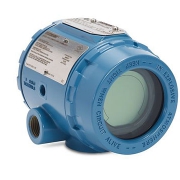
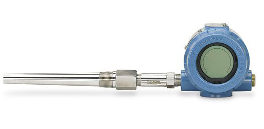
Rosemount 3144P Temperature Transmitter

The Rosemount 3144P Temperature Transmitter provides industry-leading accuracy, stability, and reliability for your temperature measurements. It features a dual-compartment housing to ensure reliability and advanced diagnostics to keep your measurement point up and running.

When combined with Rosemount X-well Technology and the Rosemount 0085 Pipe Clamp sensor, this transmitter can provide accurate measurement of process temperature, eliminating the need for a thermowell or process penetration.

The industry-leading Rosemount 3144P Single Point Temperature Transmitter delivers unmatched field reliability and innovative process measurement solutions and diagnostics Transmitter features include:

  • Temperature measurement assembly with Rosemount X-well Technology (option code PT)
  • Dual and single sensor input capabilities
  • Transmitter-sensor matching (option code C2)
  • Integral transient protector (option code T1)
  • IEC 61508 Safety Certificate of Compliance (option code QT)
  • Advanced sensor and process diagnostics (option codes D01 and DA1)
  • Large, easy to read LCD display (option code M5)
  • “Assemble to Sensor” option (option code XA)

technical specification

Material

  • Aluminum
  • Stainless steel

Connection Size

  • ½–14-in. NPT
  • M20 x 1,5 (CM20)
  • PG 13.5 (PG11)
  • JIS G ½

Transmitter output

  • 4—20 mA with a digital signal based on HART Protocol
  • FOUNDATION Fieldbus digital signal (includes three AI function block and backup link active scheduler)

Measurement Configuration

  • Single-sensor input
  • Dual-sensor input

Display

  • The large LCD display with percent range graph and buttons/switchesDiagnostics

Calibration Options

  • Transmitter-sensor matching (Callendar-Van Dusen constants), custom trim

Certifications/Approvals

  • SIL 2/3 certified to IEC 61508 by an independent 3rd party, hazardous location, marine type, see full specs for a complete list of certifications

Data Sheet

Differential pressure Endress+Hauser

Differential pressure Endress+Hauser

Differential pressure Endress+Hauser

Whether pressure, level or flow, today pressure measurement technology is often used for measuring liquids, pastes, and gases. With a wide range of sensor technology Endress+Hauser offer instruments with the perfect fit for any kind of application.

Differential pressure transmitters with piezoresistive pressure sensors and welded metallic membrane or electronic dp or diaphragm seal are used mostly in the process industry. Deltabar offers continuous level measurement in liquids as well as volume or mass flow measurement using primary elements. It is also possible to do filter monitoring with the differential pressure transmitter.

Beside the devices with silicon or diaphragm seal for differential pressure, level, dp flow measurement, Deltabar electronic dp is a differential pressure system combining two sensor modules and one transmitter. In level applications, the high-pressure sensor (HP) measures the hydrostatic pressure. The low-pressure sensor (LP) measures the head pressure. The level or differential pressure is calculated in the transmitter using these two digital values.

Differential pressure measurement:

Measuring Principle

Silicon cell:

The operating pressure deflects the process isolating diaphragm and a fill fluid transfers the pressure to a resistance bridge (semiconductor technology). The pressure-dependent change in the bridge output voltage is measured and evaluated.

Diaphragm seal:

The operating pressure acts on the process isolating diaphragm of the diaphragm seal and is transferred to the process isolating diaphragm of the sensor by a fill fluid.

Primary elements:

contact your local Sales Center

Benefits

  • Easy menu-guided commissioning via local display, 4 to 20mA with HART, PROFIBUS PA, FOUNDATION Fieldbus
  • Easy process adaptation to impulse line high-pressure/low-pressure change via an electric switch on the main electronics
  • Compact design and modular concept for easy replacement of display or electronics
  • Process pressure up to SIL2 certified to IEC 61508 and IEC 61511
  • Global usage thanks to the widest range of approvals for industries and applications

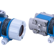
Differential pressure Deltabar PMD55

The Deltabar PMD55 differential pressure transmitter with piezoresistive sensor and the welded metallic membrane is typically used in the process or environmental applications for continuous measurement of pressure differences in liquids, vapors, and gases. Quick Setup with adjustable measuring range allows simple commissioning, reduces costs and saves time. SIL2 according to IEC 61508 / IEC 61511.

Field of application

For level, volume or mass measurement in liquids, differential pressure monitoring, e.g. of filters and pumps as well as flow measurement (volume or mass flow) in conjunction with primary elements in gases, vapors, and liquids.

  • Process connections: Threads
  • Process temperature: -40 to 85°C (-40 to 185°F)
  • Measuring ranges: 0.5mbar to 40bar (0.0072 to 600psi)
  • Accuracy: ±0.1%, “Platinum” ±0.075% (optional)
  • International explosion protection certificates, SIL
Electronic flow switch With display WIKA

Electronic flow switch With display WIKA

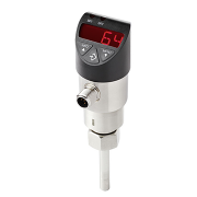
Electronic flow switch With display WIKA, for liquid media Model FSD-3

Flow switches are used for the display and monitoring of the flow of liquid and gaseous media. The instruments feature a high switching accuracy and functional safety, low switch hysteresis and continuous switch point setting by the operator.

The wide selection of WIKA flow switches also includes viscosity-compensated models and ATEX-certified instruments for use in hazardous environments.

Applications of the flow switch

  • Control of cooling lubricant systems
  • Monitoring of cooling circuits
  • Control of filter units
  • Dry run protection in pumps

Special features of the flow switch

  • Reliable flow monitoring of liquid media
  • Switching and analog outputs for flow, temperature, and diagnostics
  • Easily parameterisable via the local display
  • Free from wear, without any moving parts in the medium

The successful design and the excellent functionality of the WIKA switch family were already confirmed by winning the “iF product design award” for the pressure switch model PSD-30.

The robust LED display has been designed using 9 mm high characters (the largest possible) and with a slight incline in order to make reading the flow as easy as possible from greater distances.
The 3-key operation makes simple, intuitive menu navigation possible, with no need for additional assistance. The menu navigation conforms to the VDMA standard.

Free from wear

The FSD-3 flow switch operates on the basis of the calorimetric measuring principle. This guarantees a wear-free flow measurement without any moving parts in the medium.

Flow monitoring of liquid media

The FSD-3 flow switch enables the reliable and process-safe monitoring of the flow of liquid media. When the flow is above or below the set value, the switching output activates the downstream regulator or control. Damage and production losses through degradation of pumps, tools, and spindles can thus be avoided.

Temperature monitoring

The medium temperature can be monitored by means of a temperature output, without the need for equipping another measuring location.

Diagnostic function

The optional diagnostic function of the flow switch reliably outputs a warning when a sensor defect is detected. The switching output can be used to trigger a downstream safety function.

Flow

  • Water: 5 … 150 cm/s
  • Oil: 3 … 300 cm/s

Temperature (option)

  • -20 … +85 °C (-4 … +185 °F)

Display

  • 14-segment LED, red, 4-digit, 9 mm (0.35 in) character size Display can be turned electronically by 180°

Power supply

  • DC 15 … 35 V