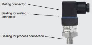
Pressure Transmitter WIKA Model A10
Pressure Transmitter WIKA Model A10
A pressure transducer is a transducer that converts pressure into an analog electrical signal. There are various types of pressure transducers, such as a capacitive pressure transducer, digital output pressure transducer, voltage/current output pressure transducer, and many others.
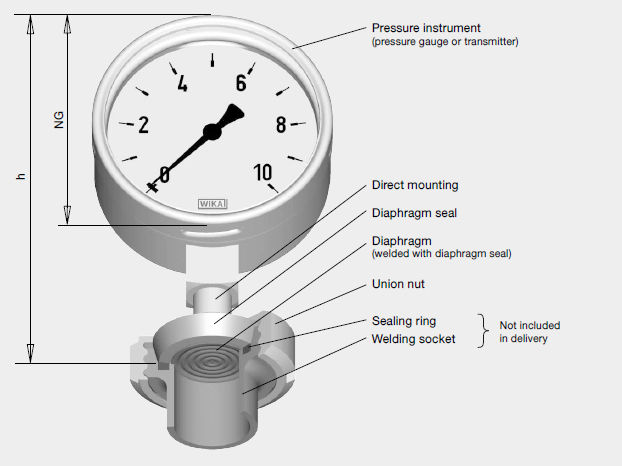
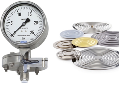
However, in all types of pressure transducers, the conversion of pressure into an electrical signal is achieved by the physical deformation of the diaphragm of the pressure, which then produces an electrical resistance change proportional to the pressure.
The Pressure Transmitter WIKA Model A10 is precision engineered and manufactured to fit many industrial and OEM pressure measurement applications.
The rugged design provides resistance to vibration, shock, wide temperature variations, RFI and other extreme environmental conditions that are typical of industrial and OEM applications.
Performance and reliability are enhanced by the all stainless steel welded measuring cell that eliminates the need for soft sealing materials that may deteriorate over time. The state-of-the-art manufacturing and assembly process increases the long term reliability of the A-10.
Primary applications include process control and automation, hydraulics, pneumatics and machine controls.
Applications
- Mechanical engineering
- Machine tools
- Process control and automation
- Hydraulics and pneumatics
- Pumps and compressors
Technical Features
Gauge Pressure (Bar)
0 … 0.05 / 0 … 0.1 / 0 … 0.16 / 0 … 0.25 / 0 … 0.4 / 0 … 0.6 / 0 … 1 / 0 … 1.6 / 0 … 2.5 / 0 … 4 / 0 … 6 / 0 … 10 / 0 … 16 / 0 … 25 / 0 … 40 / 0 … 60 / 0 … 100 / 0 … 160 / 0 … 250 / 0 … 400 / 0 … 600 / 0 … 1,000
Absolute Pressure (Bar)
0 … 0.1 / 0 … 0.16 / 0 … 0.25 / 0 … 0.4 / 0 … 0.6 / 0 … 1 / 0 … 1.6 / 0 … 2.5 / 0 … 4 / 0 … 6 / 0 … 10 / 0 … 16 / 0 … 25
Vacuum and +/- measuring range (Bar)
-0.025 … +0.025 / -0.05 … 0 / -0.05 … +0.05 / -0.05 … +0.15 / -0.05 … +0.2 / -0.05 … +0.25 / -0.1 … 0 / -0.1 … +0.1 / -0.15 … +0.15 / -0.16 … 0 / -0.2 … +0.2 / -0.25 … 0 / -0.25 … +0.25 / -0.3 … +0.3 / -0.4 … 0 / -0.5 … +0.5 / -0.6 … 0 / -1 … 0 / -1 … +0.6 / -1 … +1.5 / -1 … +3 / -1 … +5 / -1 … +9 / -1 … +15 / -1 … +24
Output Signals
- Current (2-wire): 4 … 20 mA
- Voltage (3-wire): DC 0 … 10 V
- Voltage (3-wire): DC 0 … 5 V
- Voltage (3-wire): DC 1 … 5 V
- Ratiometric (3-wire): DC 0.5 … 4.5 V
Voltage supply
- 4 … 20 mA: DC 8 … 30 V
- DC 0 … 10 V: DC 14 … 30 V
- DC 0 … 5 V: DC 8 … 30 V
- DC 1 … 5 V: DC 8 … 30 V
- DC 0.5 … 4.5 V: DC 8 … 30 V
- DC 0.5 … 4.5 V ratiometric: DC 5 V ± 10 %
Temperature Ranges
- Ambient: 0 … +80 °C
Process Connections
- G ⅛ B – G ¼ B – G ¼ female – G ¼ female, with flange connection – G ⅜ B – G ½ B
- G ¼ A – G ½ A – M14 x 1.5
- ⅛ NPT – ¼ NPT – ¼ NPT female – ½ NPT
- R ¼ – R ⅜ – R ½
- PT ¼ – PT ½ – PT ⅜
Ingress protection
- IP65
- IP67
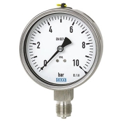
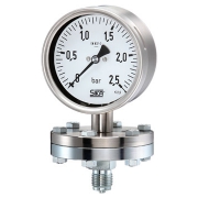
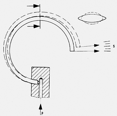 The pressure gauge is an instrument used to measure or display pressure.Wika Pressure Gauge 232.50 is bourdon tube pressure gauges are the most frequently used mechanical pressure measuring instruments.
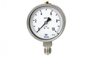
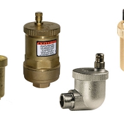
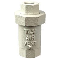
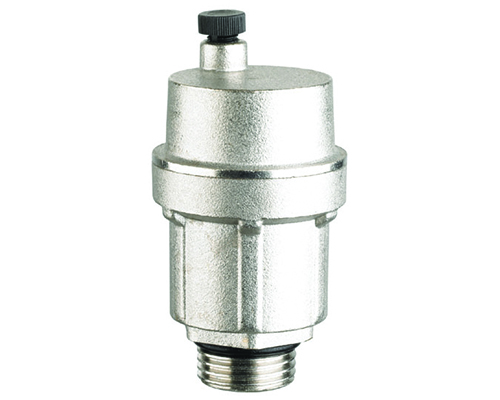 Automatic Air Vent
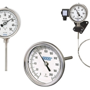
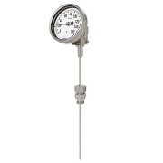
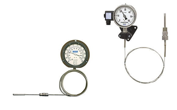 Gas-actuated Thermometers
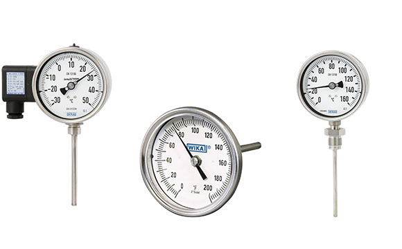 Bimetal Thermometer