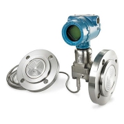
Rosemount 3051SAL Level Transmitter
Rosemount 3051SAL Level Transmitter
Make reliable pressure measurements in extreme conditions with the Rosemount 3051SAL Level Transmitter, a best-in-class solution that offers enhanced capabilities for pressurized and vented tank level measurements. This transmitter is safety certified and engineered with advanced diagnostics for increased insight. Designed to allow direct mounting, remote mounting, balanced systems and Tuned-System™ assemblies, this device can meet a variety of demands and process requirements for level applications.
Features of Rosemount 3051S DP Level Technology
1- ERS System
Electronic Remote Sensor (ERS™) Systems provide DP Level measurements by calculating differential pressure from individual pressure readings. This solution eliminates the need for long capillaries and heat tracing, reducing response time by up to 90%. The sensor system is synchronized for DP calculation, easily connects with cable, and can be independently installed and serviced for simple installation and maintenance.
2- Thermal Range Expander
Thermal Range Expander enables pressure and level measurements in high-temperature processes. This seal system uses two different fill fluids, extending the operating range of the transmitter from temperatures ranging from -75 °C (-103 °F) to 410 °C (770 °F). With an improved response time of up to 46%, thermal range expanders simplify installation and reduce cost by eliminating impulse piping and heat tracing.
3- Wireless Technology
With Wireless Technology, you can add new measurement points easily and cost-effectively in many areas of the plant including those that were previously inaccessible. This information allows you to better optimize your level measurements and reduce personnel exposure to hazardous environments. Get coverage over larger areas with long-range communication options up to 1 km (2/3 mi) between devices.
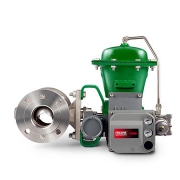
4- Diaphragm Seal System
The Diaphragm Seal System protects transmitters from hot, cold, corrosive, erosive or viscous processes. Seals are available with differential, gauge and absolute pressure transmitters. Advanced welding and assembly techniques prevent weld corrosion and improve seal strength to deliver reliability and performance in the toughest applications.
5- Expanded Capabilities
The Rosemount 3051S enhanced features offer a scaled process variable, enabling this device to convert pressure units to customized, user-defined units. Process pressure or temperature alerts can also be configured as well as alerts of abnormal process conditions. In addition, the 3051S features remote mount LCD display capabilities, allowing direct mounting of the device while keeping the local display in a convenient location.
6- Seal System Construction
1- Universal Connection
- Welded capillary/instrument connection eliminates leaks and improves reliability
2- Advanced Weld Techniques
- Engineered to prevent weld corrosion
- Improves seal reliability
3- Backup Diaphragm Pattern
- Matches pattern of diaphragm
- Helps diaphragm maintain original form
- Reduces oil volume for improved performance
4- Recessed Diaphragm
- Protects diaphragm from installation damage
- Minimize gasket induced errors
- Protects diaphragm from installation damage
- Prevents zero offset pressure on the diaphragm from the off-centered gasket
Specifications
Max. Operating Pressure
- Up to 10,000psi (689.48 bar)
Process Temperature Range
- Based on fill fluid – Maximum 770°F (410°C), Minimum -157°F (-105°C)
Communication Protocol
- 4-20 mA HART®
- WirelessHART®
- FOUNDATION™ Fieldbus
Seal System Type
- Direct Mount
- Remote Mount
- Tuned-System
- Balanced System
Transmitter Connection
- Welded-Repairable
- All Welded
Process Connection
- Flanged: ANSI/ASME, EN/DIN, GOST, & JIS
- Threaded: NPT, DIN, ISO
- Hygienic
Process Wetted Material
- 316L SST
- Alloy C-276
- Alloy 400
- Tantalum
- Gold-plated Alloy 400
- Gold-plated 316L SST
Diagnostics
- Basic Diagnostics
- Loop Integrity
- Process Intelligence
- Plugged Impulse Line
Certifications/Approvals
- SIL 2/3 certified to IEC 61508 by an independent 3rd party
- NACE®
- 3A
- hazardous location
![]()