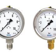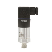
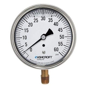
Liquid Filled Pressure Gauge
Liquid Filled Pressure Gauge
There are two main types of pressure gauges:
- Liquid Filled Pressure Gauge
- Dry Pressure Gauge
Dry pressure gauges are the most important part of the industrial and commercial parts world. Look at most air compressors. Many industrial machines and even some of the fancier bicycle pumps will have a dry gauge. Dry gauges do have some drawbacks, though.
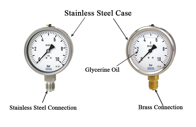
Liquid-filled gauges are generally preferred over dry gauges for two reasons: performance and ROI. Liquid-filled gauges are filled with a liquid, usually, glycerin or silicone oil and are designed to perform optimally in less-than-ideal conditions.
Why Liquid Filled?
Liquid-filled gauges have longer lives than traditional (non-hermetically-sealed) gauges because of their viscous fluid filling. Over time, this design advantage results in costs savings due to lowered instrumentation costs as well as lessened unscheduled downtime.
Internal liquids protect against severe temperature fluctuations and vibrations—major factors in the breakdown of regular gauges. Because they dampen temperature spikes and vibrations.
In traditional gauges, condensation build-up results in visibility issues. This can be a crucial (and costly) flaw in high-humidity environments—an unreadable gauge is a worthless gauge. Liquid-filled gauges are designed to prevent moisture from entering not only the body casing but also the inside of the case lens.
Because they are sealed and constructed to meet rugged specifications, liquid-filled gauges are commonly used in highly corrosive chemical processes or in manufacturing or refining processes, and where products must be transported, stored, or handled in extreme temperature conditions.
Advantage of a Liquid Filled Gauge
- It’s an inexpensive solution and in many cases comes standard on a gauge
- It helps increase the life of the gauges by dampening as well as lubricating the mechanical parts of a pressure gauge
Disadvantage of a Liquid Filled Gauge
- Discoloration (darkening or yellowing) of glycerin over time due to exposure of UV rays or extreme temperature changes
- Standard Glycerin is really only good down to 20 degrees Fahrenheit. It is not recommended for cold environments
- Risk of leakage
- Pressure can build up in the case due to expansion and contraction of fluid from temperature changes (usually small, 1 PSI or so) affecting the accuracy of the reading as well as bring the needle off of zero