Valve Symbol

Valve Symbol

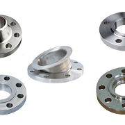
A valve regulates, directs, or controls the flow of a fluid by opening, closing, or partially obstructing passageways in a piping system. This category includes rotameters, orifices, and other types of valves.

Piping and instrumentation diagrams, or P&IDs, are used to create important documentation for process industry facilities. The shapes in this legend are representative of the functional relationship between piping, instrumentation, and system equipment units.
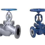
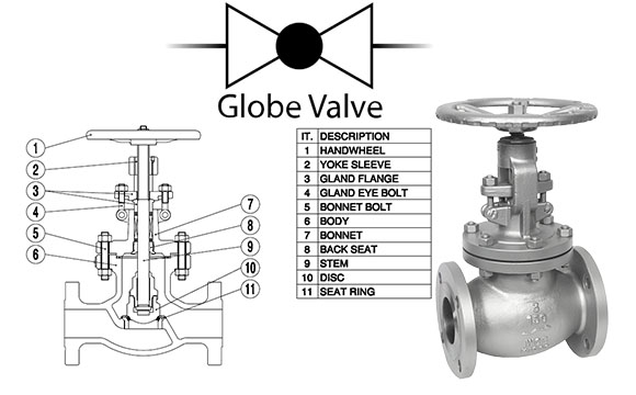
Globe Valve

A globe valve is a linear motion valve used to stop, start, and regulate the fluid flow. The globe valve disk can be removed entirely from the flow path, or it can completely close the flow path. During opening and closing of globe valve, disc moves perpendicularly to the seat.
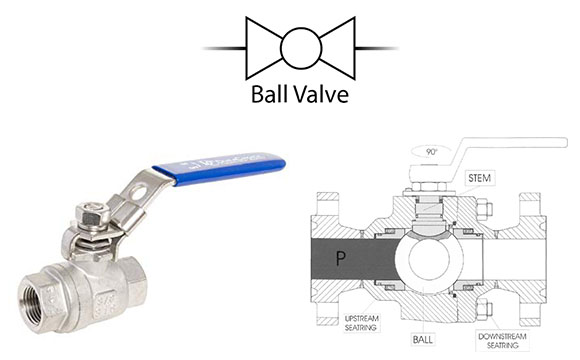
Globe Valve

Ball Valve

Ball valves are quarter-turn, straight-through valves that have around closure element with matching rounded seats that permit uniform sealing stress. The valve gets its name from the ball that rotates to open and close the valve. Ball valves are used in situations where tight shut-off is required. They are wide duty valves, able to transfer gases, liquids, and liquids with suspended solids (slurries).
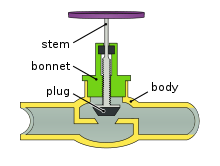
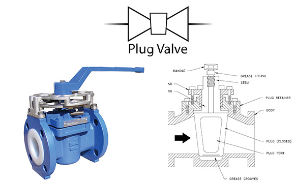
ball valve

Plug Valve

A plug valve is shaped like a cylinder or cone and can be rotated inside the valve body to control flow of fluids. Plug valves have one or more hollow passageways often placed horizontally to allow ease of flow through the valve when open. The most common type of plug valve is the 2 port model with an open and closed position. The two ports are usually located on opposite sides of the valve with one passageway leading from inbound to outbound and the stem and handle located on the top. A plug valve also uses a quarter turn valve, which is useful where the quick and frequent operation is essential. The valve ends can be flanged, hub type, or butt weld.
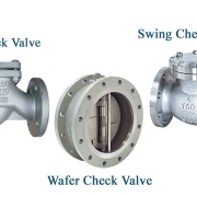
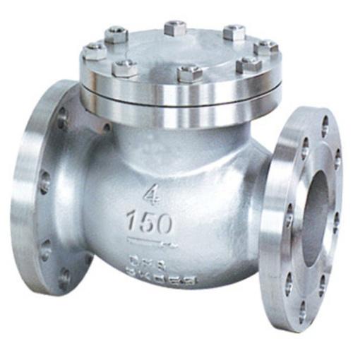
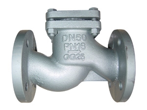
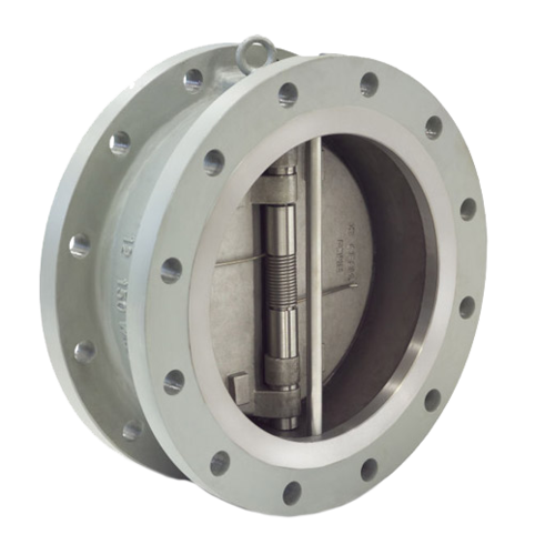
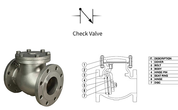
plug valve


Check Valve

The valve that used to prevent backflow in a piping system is known as a check valve. It is also known as a non-return valve or NRV. The pressure of the fluid passing through a pipeline opens the valve, while any reversal of flow will close the valve. It allows full unobstructed flow and automatically shuts as pressure decreases. The exact operation will vary depending on the mechanism of the valve.
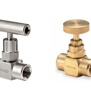
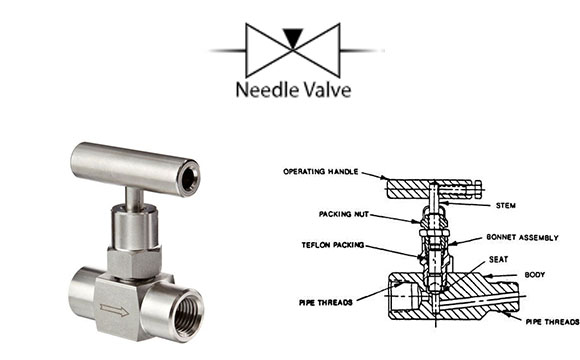
Check Valve

Needle Valve

A needle valve is a manual valve that used where continuous throttling of flow is required for regulation. Needle valves are similar to the globe valve in design with the biggest difference is the sharp needle like a disk.

Needle valves are designed to give very accurate control of flow in small diameter piping systems. They get their name from their sharp-pointed conical disc and matching seat.
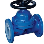
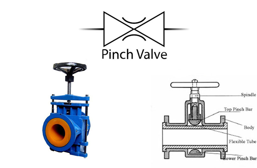
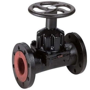
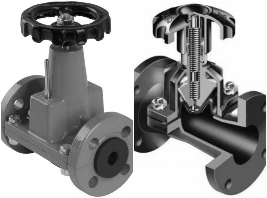
Needle Valve

Pinch Valve

A Pinch Valve is an economical piece of equipment that works like a tap. It has an on/off function, to shut off, allow or control the flow of any media passing through it. The Pinch Valve is made up of three parts: Body / Housing, Internal rubber sleeve, End connections.

The rubber sleeve inside the body of the valve is the part that closes it. When in the open position, the Pinch Valve has a full and true bore. To close the valve, air pressure is supplied into an air nipple on the outer body, which then travels through into the internal part of the valve, pushing down onto the rubber sleeve which fully collapses and closes tightly.
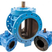
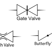
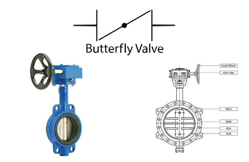
Butterfly Valve

A butterfly valve is a flow regulating disc valve. A butterfly valve consists of a circular disc or plate built with a stem through the middle or attached offset. When opened, the disc pivots 90 degrees in the valve bore, aligning with the flow, creating a nearly unrestricted flow path. Butterfly valves operate similarly to ball valves in their 90-degree rotation and allow for quick shutoff.
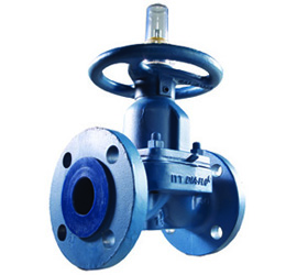
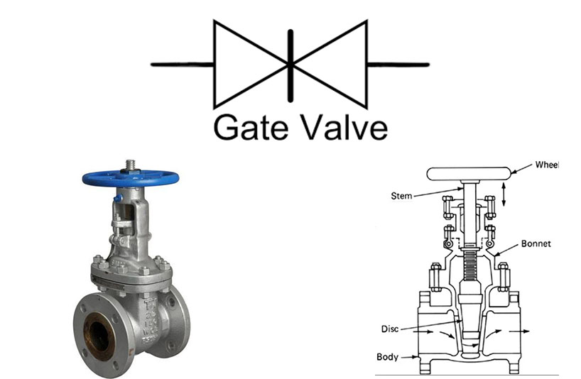
butterfly valve

Gate Valve

Gate valves are designed for fully open or fully closed service. They are installed in pipelines as isolating valves, and should not be used as a control or regulating valves. Operation of a gate valve is performed doing an either clockwise to close (CTC) or clockwise to open (CTO) rotating motion of the stem. When operating the valve stem, the gate moves up- or downwards on the threaded part of the stem.

Gate valves are often used when minimum pressure loss and a free bore is needed. When fully open, a typical gate valve has no obstruction in the flow path resulting in a very low-pressure loss, and this design makes it possible to use a pipe-cleaning pig. A gate valve is a multiturn valve meaning that the operation of the valve is done by means of a threaded stem. As the valve has to turn multiple times to go from open to closed position, the slow operation also prevents water hammer effects.

Gate Valve

Pinch Valve Advantage and Disadvantage

Pinch Valve Advantage and Disadvantage

Pinch Valve Advantage and Disadvantage

Pinch Valve is made using a metal frame that houses a rubber wear sleeve and a shut-off mechanism. The rubber sleeve is the only part that comes in contact with the flowing media; this significantly minimizes the chances of contamination within the system.

Depending on the application, the rubber sleeve is hand-built with different kinds of rubber compounds to make it suitable for the required application. Pinch valves have a full bore design with no mechanical parts and quick closing mechanism. They require little to no maintenance, additionally changing the rubber sleeve is very easy.

Relatively inexpensive linear motion pinch valve consists of a flexible tube (rubber tubing) that is mechanically pinched from the outside of the valve body.

Pinch valves are suitable for on-off and throttling services. However, the effective throttling range is usually between 10% and 95% of the rated flow capacity. Pinch valves are ideally suited for the handling of slurries, liquids with large amounts of suspended solids, and systems that convey solids pneumatically.

Because the operating mechanism of the valve is completely isolated from the fluid, these valves also find application where corrosion or metal contamination of the fluid might be a problem.

Pinch valves benefits

Some of the benefits of pinch valves are:

  • Minimal turbulence
  • Low maintenance
  • Excellent drainage
  • Very Clean
  • Low weight
  • Inexpensive
  • Low airborne contaminants

Pinch valves are preferred over other types of valves because of their low cost, easy maintenance, and full bore design offering zero leakage. They can be used in a diverse range of applications.

Advantages of Pinch Valve

  • It can be used for application where corrosion or metal contamination of the fluid might be a problem. Flow from the valve is straight without any obstruction.
  • There are no internal moving parts in contact with the fluid hence, low maintenance cost.
  • Inexpensive due to simple construction

Disadvantages of Pinch Valve

  • It cannot be used in high temperature-pressure applications and gas media.

Application of Pinch Valve

  • Gauge protection: Install directly in the fluid line or put a tee in the line and attach the valve to the leg of the tee.
  • Motion control: Hold rods and shafts in a fixed position. Use for linear or rotational motion control.
  • Pneumatic conveying: Control fluidized dry material.
  • Pressure relief: Use actuation pressure to close the valve at “normal” operation pressures for the system.
  • Surge protection: Modulate surges in pressure or flow rate in a piping system.
  • Throttling: Valves can maintain a lower actuation/controlled material pressure differential that is required for complete closure.
  • Vacuum receiver: Can eliminate the need for the periodic shutdown of the system to empty a receiver.

Plug Valves Advantages and Disadvantages

Plug Valves Advantages and Disadvantages

A Plug Valve is a quarter-turn rotational motion Valve that use a tapered or cylindrical plug to stop or start the flow. In the open position, the plug-passage is in one line with the inlet and outlet ports of the Valve body. If the plug 90° is rotated from the open position, the solid part of the plug blocks the port and stops the flow. Plug valves are similar to Ball valves in operation.

Type of Plug Valve

  • lubricated plug valve
  • non-lubricated plug valve
  • eccentric plug valve
  • lift-type plug valve

Plug Valve Application

Plug valves are a type of flow control valve that allows the user to increase or decrease flow by rotating the handle or other similar operation. The user may have to adjust the valve to the desired flow rate, with the valve able to hold the flow rate consistently and reliably.

Other popular flow control valves include needle and fine metering valves, but they generally have more moving parts than plug valves, which makes them more expensive and harder to maintain.

Plug valves are typically used in applications where flow must be controlled and changed on a regular basis and where the user must have access to the valve.

Plug valves should not be used in applications where a constant, steady flow is required or where the valve does not need to be readily accessible.

Quarter-turn plug valves are the most common and involve a simple quarter turn on a handle to open and close the valve. They are economically priced and are commonly used for applications involving low-pressure throttle.

Advantages of Plug Valve 

  • one-piece valve body, top-loading design, simple structure, convenient maintenance, no leakage, supporting higher-strength pipe system.
  • The medium in the chemical process has strong corrosion resistance. In the chemical field, corroded valve body often can be seen. Therefore, the valve in the application of chemical process must have strong permeability and resistance to intergranular corrosion. The body of plug valve should be high-level casting, with casting quality of class II and precision of grade V.
  • Really simple internals. The plug is completely covered by the bushing. Body and plug have no wear. Replacing simple and economic bushing or top sealing device can complete the maintenance and update of the valve. Plug valve can reach long-term use requirement of 300 ℃, which has a considerable competitive edge compared with a ball valve that belongs to this application.
  • Top surface and flange are all the processing surface of the plug valve. Other parts are all one-time casting molding. The inside of the valve body has no processing. Comparing with the ball valve, it has the advantages of lower machining allowance. Especially, when the material is INCONEL, MONEL, HARTZ alloy, plug valve has the distinct advantage of price.
  • According to the user’s demand, various designs of plug valve can achieve a specific function. Plug valve is the best one of customized products. Plug valve is easy to cater to custom design, can be made into three-way, four-way, five-way and six-way valve; double valve group or valves group; all kinds of jacket requirements, etc.. For example, the six-way distribution valve used in the polyester industry is designed according to the requirements of patent owners, while the ball valve is difficult to make in line with custom design.
  •  Now, no clearance and face sealing is still the unique features of the plug valve. Although it has the design of the clearance like ball valve’s, the clearance just can be reduced to 1 ~ 3 mm at the most, which can’t achieve the application advantages of coated surface sealing. This characteristic of plug valves enables it to deal with a lot of harsh media, such as easy crystal and viscous fluid or those medium containing catalyst particles and deposit.
  • Coated bushing provides the characteristics of face sealing. It can be strictly controlled in accordance with the test requirements of zero leakage of API 598 soft sealing valve seat, achieving or sealing requirements of a stem of TA Luft or ISO 15848.
  • Comprehensive characteristics of plug valve are long service life, high reliability. It is a good choice for a lot of corrosive, abrasive and toxic fluid as well as continuously operated device. It has the application advantages and extensive applicability in the field of chemical industry.

Disadvantages of Plug Valves

  • The design of face sealing improves the requirements for driving torque. In the case of needing to be equipped with pneumatic actuators, compared with ball valve, it will cost much more. Such as the PP process, the main shut-off valve of it is the plug valve, rather than the ball valve, but the high-frequency switching valve is a ball valve. Therefore, basically, the pneumatic plug valves are applied to the key cut-off position. Plug valve is not recommended to apply it to the occasion of adjustment since the high-frequency switching is not the advantage of it. It is the cut-off valve of high reliability.
  •  In some applications, the incorrect choice of bushing material or improper design of the release area of bushing deformation may cause swelling for PTFE bushing materials, leading to the change of driving torque for several times.
  • Though the investment of plug valve is more than ball valve, as its advantages of reliability and the total cost of the life cycle are gradually accepted by users, more and more users will continue to use the plug valve.
Diaphragm Valve

Diaphragm Valves

Diaphragm Valves

Diaphragm Valves use a ‘pinching’ method to stop the valve flow using a flexible diaphragm. They are available in two types: weir and straight-way. The most commonly seen of the two is the weir-type. This is because the straight-way type requires additional stretching of the diaphragm, which can shorten the diaphragm’s life-span.

One of the major advantages of using diaphragm valves is that the valve components can be isolated from the process fluid. Similarly, this construction helps prevent leakage of the fluid without the use of a gland seal (packing) as seen in other types of valves.

On the other hand, the diaphragm becomes worn more easily and regular maintenance is necessary if the valve is used on a regular basis. These types of valves are generally not suited for very high-temperature fluids and are mainly used on liquid systems.

Diaphragm valves are used on shut-off and throttling service for liquids, slurries and vacuum/gas.

The seal is achieved by a flexible membrane, usually elastomer, and possibly reinforced with a metal part. The membrane is tensed by the effect of a stem/compressor with linear movement until contact is made against the seal of the body.

The operating parts of the diaphragm valve are isolated from the flow. This makes this valve suitable for viscous flows and also hazardous, abrasive and corrosive flows as its sealing system avoids any contamination towards or from the environment.

Diaphragm valves are available in a wide variety of metals, solid plastics, plastic, rubber and glass linings. They are well suited to the handling of multiple chemical applications both clear fluids as well as slurries.

The diaphragm valve has an extended use for applications at low pressures and slurry fluid where most other kinds of valves corrode or become obstructed.

There are two types of diaphragm valves:

1- Weir

  • The Weir Diaphragm valve can be used for either off/on and throttling services


2-Straightway

  • named also Straight-Thru is only used for on/off services.

Advantages of Diaphragm Valve

  • Can be used as on-off and throttling service valves.
  • Offer good chemical resistance due to a variety of linings available.
  • Stem leakage is eliminated.
  • Provides bubble-tight service.
  • Does not have pockets to trap solids, slurries, and other impurities. It is suitable for slurries and viscous fluids.
  • These valves are particularly suitable for hazardous chemicals and radioactive fluids.
  • These valves do not permit contamination of flow medium, thus they are used extensively in food processing, pharmaceutical, brewing, and other applications which cannot tolerate any contamination.

Disadvantages of Diaphragm Valve

  • The weir may prevent full drainage of piping.
  • Working temperatures and pressures are limited by the diaphragm material. Generally, the pressures are limited to 200 psi (1380 kPa) and temperatures up to 400 F (204 C).
  • The diaphragm may also limit the hydrostatic pressure.
  • The diaphragm may experience erosion when used extensively in severe throttling service containing impurities.
  • Diaphragm valves are available in limited sizes, usually NPS ¹⁄₂ to 12 (DN 15 to 300).

Typical Application of Diaphragm Valves

  • Clean or dirty water and air service applications
  • De-mineralized water systems
  • Corrosive applications
  • Radwaste systems in nuclear facilities
  • Vacuum service
  • Food processing, pharmaceutical, and brewing systems


Butterfly Valve

Butterfly Valve Advantages and Disadvantages

Butterfly Valve Advantages and Disadvantages

A Butterfly Valve is a shut-off valve with a relatively simple construction. In a closed position, the disc blocks the valve bore while in an open position, the disc turn allows flow. A quarter turn takes the valve from fully open to a fully closed position or the opposite, and thus the butterfly valve allows for quick opening and closure.

Butterfly valves can be used for a broad range of applications within water supply, wastewater treatment, fire protection, and gas supply, in the chemical and oil industries, in fuel handling systems, power generation etc. Some of the advantages for this type of valve are the simple construction not taking up too much space, and the lightweight and lower cost compared to other valve designs.

The valves can be operated by handles, gears or actuators according to any specific need.

Types of Butterfly Valves

Butterfly valves have been around for a long time, and are used for a variety of applications. They made their first appearance during the 1930s, and have been utilized by several industries ever since.

Often made out of cast iron, butterfly valve’s name is based on the functionality of its disc. There are a few different types of butterfly valves, however, they fall into two basic types – Lug and Wafer valves.

LUG BUTTERFLY VALVE

The lug version of the butterfly valve’s design is similar to a 3-piece ball valve in that one end of the line can be taken off without having an effect on the opposing side. This can be executed by using threaded inserts, flanges, along with two sets of lugs (bolts) that don’t utilize nuts since each flange features its own bolts. It’s also important to note that you don’t need to shut down the entire system in order to clean, inspect, repair, or replace a lug butterfly valve (you would need to with a wafer butter valve).

WAFER BUTTERFLY VALVE

A wafer butterfly valve’s function is to retain a seal to protect against dual-directional pressure differential in the flow of fluid. In other words, the wafer version of butterfly valves was designed to hold a tight seal, safeguarding against bi-directional pressure differential in order to avoid any backflow in systems that have been manufactured for uni-directional flow.

This is accomplished by using a tightly fitted seal, such as an O-ring, gasket, precision machined, along with a flat valve face on the downstream and upstream sections of the valve.

Both lug and wafer butterfly valves are used in a number of applications for industrial sectors that include food processing, pharmaceutical, chemical, oil, water as well as wastewater management.

Butterfly valves, for the most part, have replaced ball valves in a lot of industries. This is especially the case for those dealing with petroleum because they are less expensive and easy to install. It’s important to note that pipelines that contain butterfly valves can’t be ‘pigged’ for cleaning. “Pigging” is the process of making use of devices referred to as “pigs” to carry out a variety of maintenance operations.

BUTTERFLY VALVE APPLICATIONS

  • Cooling water, air, gases, fire protection.
    • Slurry and similar services.
    • Vacuum service.
    • High-pressure and high-temperature water and steam services.
    • Compressed air or gas applications.

Advantages of a Butterfly Valve

  • The compact design requires considerably less space, compared to gate, globe, or other valves.
  • Light in weight.
  • Quick acting; as a quarter-turn valve, it requires less time to open or close.
  • Butterfly Valve is available in large sizes, ranging from NPS 1¹⁄₂ (DN 40) to over NPS 200 (DN 5000).
  • They have low-pressure drop and high-pressure recovery.
  • Provide bubble-tight service.

Disadvantages of a Butterfly Valve

  • Butterfly Valve Throttling service limited to low differential pressure.
  • Cavitation and choked flow are two potential concerns.
  • Butterfly Valve disc movement guides and affects by flow turbulence


Needle Valve

Needle Valve

Needle Valve

A Needle Valve is used to make relatively fine adjustments in the amount of fluid flow. The distinguishing characteristic of a needle valve is the long, tapered, needle-like point on the end of the valve stem. This “needle” acts as a disk.

The longer part of the needle is smaller than the orifice in the valve seat and passes through the orifice before the needle seats. This arrangement permits a very gradual increase or decrease in the size of the opening. Needle valves are often used as component parts of other, more complicated valves. For example, they are used in some types of reducing valves.

Needle Valve Application

Most constant pressure pump governors have needle valves to minimize the effects of fluctuations in pump discharge pressure. Needle valves are used in almost every industry in an incredibly wide range of applications – anywhere control or metering of steam, air, gas, oil, water or other non-viscous liquids is required.

Needle Valve application in industries

  • Zoological sciences
  • Gas and liquid dispensation
  • Instrumentation control
  • Cooling
  • Power generation
  • Automatic combustion control systems
  • precise flow regulation

Needle valves can also be used as on/off valves or for throttling service.

ADVANTAGES OF NEEDLE VALVES

Needle valves give us great control over the flow rate of a liquid or gas which in reality, gives us the luxury to consume the fuel according to our desire. For example, in a motorcar engine, it is a needle valve which is responsible to regulate the fuel flow rate.

These valves can work both ways. Whether you want to increase the flow rate or decreasing it.

Besides the control on flow rate, it also stables the pressure too. The pressure loss is on the minimum side as compared to the other same as valves that are available in the market.

DISADVANTAGES OF NEEDLE VALVES

Unlike other types, you can’t visually observe the position of the screw or the handle used to control the positioning of the screw in the valve that determines if the valve is open or closed. To tackle it, other devices are often included in the equipment design that makes it possible to monitor the flow and use the valve to adjust that flow accordingly.

Needle valve selection

Items that you should consider when selecting a needle valve:

Pressure

The working pressure is an important factor in selecting the right needle valve. Robust needle valves can handle pressures of up to 4000-5000 psi (275-413 bar) at 100°F (38°C). When still higher pressures are required, high-performance valves are available that can handle up to 10000 psi (689 bar) pressure at 100°F (38°C).

Size

Needle valves are available in a wide range of sizes and end connections. Male/female connections with inch/metric threads can be used. The most commonly available valves have the size from 2 to 12 mm or 1/8” to 2”. Using the right valve size facilitates efficient flow and system operation with fewer chances of wear and leakage.

Temperature

Needle valves can be operated at high or low temperatures. For extreme temperatures, the packing/sealing used is particularly relevant. Two most commonly used packing materials are PTFE (Teflon) for a temperature range of -65°F to 450°F (-54° C to 232°C) and PEEK (Polyether Ether Ketone) for increased temperature resistance up to 600°F (315 °C).

Materials

Different materials are used in needle valve construction. The commonly used materials include brass, 304 or 316 stainless steel, carbon steel and Alloy 400 (Nickel based alloy).

Stainless steel is widely used for its corrosion resistance, chemical stability, and high-temperature resistance. Brass needle valves are used in hydraulic systems, high-temperature applications, and gas piping. Alloy 400 is used for its high strength, corrosion resistance and used mainly in marine and chemical processing applications.


Types and application of Check Valves

Types and application of Check Valves

Check Valves , also known as non-return or one-way valves, are designed to allow fluid to flow one way in a pipeline. They’re constructed of a clapper which hangs from a hinge, the clapper shaft or pin, which is mounted to the underside of the bonnet, inside the valve body. The basic design of a check valve inhibits backflow in a line.

Check valve applications

  • Protect drinking water from contamination by backflow resulting from gravity, back siphonage or backpressure (e.g. Hose connected kitchen spray or shower hand spray).
  • Protect sensitive equipment against possible damage or contamination resulting from a reversal of flow direction (e.g. water meter, pump or filter).
  • Hold water in a system or pipe after the flow has been turned off to prevent drainage or facilitate restart (e.g. pumping systems).
  • Prevent crossover flow in systems with unequal line pressures (e.g. cold and hot water inlets in thermostatic mixers).
  • Reduce the risk of backflow or leakage in case of valve failure (e.g. solenoid valve at the inlet of an appliance).
  • Allow complex systems to function properly by ensuring unidirectional flow (e.g. multi-zone heating system or booster pumps).

Types of the Check Valve

Swing Check Valve

A hinged disc assembly is suspended from the body to allow it to move freely. This configuration minimizes pressure loss and eases the fluid flow. Swing check valves can be used for either horizontal or vertical (fluid flowing upward) pipe layouts.


Lift Check Valve

The structure of the lift check valve is the globe valve without the handwheel and any parts which related to manual operation. And have the cover in lieu of the bonnet. Because of its large fluid resistance, this valve is used primarily for small-bore applications.


Wafer Check Valve

Thanks to its wafer shaped design, this swing check valve is far thinner and lighter than conventional water hammer absorbing check valves. It features a built-in bypass circuit and superior closing action and is multifunctional high performance water hammer absorbing check valve.


Advantages and Disadvantages of Check valve

ADVANTAGES

The check valve’s operation is completely self-automated. Therefore, should a facility lose power, the valve would still function, preventing damage to pumps and other equipment, as well as other problems upstream.

DISADVANTAGES

Noise (slamming), water hammer, and reverse flow are common problems with check valves. It is very important to note, however, that these problems generally occur because of improper sizing and/or selection for the application.

These types of valves commonly (and mistakenly) selected/sized as an on/off valve would be. Doing so could cause premature wear, high-pressure drop, and increased the expenditure of pump energy as it works harder to satisfy the system.

If you’re experiencing issues with a check valve, or need to select a new one for your process, talk to an engineer experienced in the selection/sizing of these types of valves. Doing so will help your system perform at its highest efficiency while requiring a lot less maintenance.


Globe Valve

Globe Valve

Globe Valve

A globe valve regulates flow in a pipeline. It is used to control or stop the flow of liquid or gas through a pipe. Globe valves are named for their spherical body shape with the two halves of the body being separated by an internal baffle.

Working principle

When the valve is actuated to open the disk will perpendicularly move away from the seat. When compared to a gate valve, a globe valve generally yields much less seat leakage. This is because the disk-to-seat ring contact is more at right angles, which permits the force of closing to tightly seat the disk.

Globe valves can be arranged so that the disk closes against or in the same direction of fluid flow. When the disk closes against the direction of flow, the kinetic energy of the fluid impedes closing but aids opening of the valve.

When the disk closes in the same direction of flow, the kinetic energy of the fluid aids closing but impedes opening. This characteristic is preferable to other designs when quick-acting stop valves are necessary.

Advantages and disadvantages and applications of Globe valves

ADVANTAGES

  • Good shutoff capability
  • Moderate to good throttling capability
  • Shorter stroke (compared to a gate valve)
  • Available in tee, wye, and angle patterns, each offering unique capabilities
  • Easy to machine or resurface the seats
  • With disc not attached to the stem, a valve can be used as a stop-check valve

DISADVANTAGES

  • Higher pressure drop (compared to a gate valve)
  • Requires greater force or a larger actuator to seat the valve (with pressure under the seat)
  • Throttling flow under the seat and shutoff flow over the seat

applications of Globe valves

  • Cooling water systems where flow needs to be regulated
  • Fuel oil system where the flow is regulated and leak-tightness is of importance
  • High-point vents and low-point drains when leak-tightness and safety are major considerations
  • Feedwater, chemical feed, condenser air extraction, and extraction drain systems
  • Boiler vents and drains, main steam vents and drains, and heater drains
  • Turbine seals and drains
  • Turbine lube oil system and others

Positioner

Positioner

A Positioner is used on an actuator (hydraulic or pneumatic) to provide feedback to the controller in response to the required and actual movement of the valve stem. This ensures the valve responds to system requirements.

Valve positioners compare a control signal to a valve actuator’s position and move the actuator accordingly. They are used with both linear valves and rotary valves. Valve positioners are used when the 0.2 to 1 bar pressure in the diaphragm chamber is not able to cope with friction and high differential pressures.

Valve positioners are usually mounted on the yolk or top casing of a pneumatic actuator for linear control valves, or near the end of the shaft for rotary control valves. For either configuration, the positioner is connected mechanically to the valve stem or valve shaft. This allows for the valve’s position to be compared with the position requested by the controller. When a control signal differs from the valve actuator’s position, the valve positioner sends the necessary feedback to move the actuator until the correct position is reached.

There are different types of control valve positioners

  • pneumatic positioner
  • Electro-pneumatic valve positioner
  • Electronic positioner


  • Pneumatic positioners. These devices receives a pneumatic (air) signal from the controller and output a pneumatic signal to the actuator.
  • Analog, or electro-pneumatic, positioners. Here, the input signal is electrical, rather than pneumatic.
  • Digital, or smart, positioners. These positioners also receive an electrical signal, but it’s digital as opposed to analog.
  • Digital positioners came on the scene about 20 years ago, but they only really started gaining popularity recently as automation has started to take off in plants and along pipelines.
  • The main reason digital positioners are popular is that they can do much more than just control the position of the valve. The newest positioners on the market can also collect data about the valve to automatically alert users about how the valve and its assembly are performing, and even aid in diagnostics and maintenance.
  • Since they have fewer mechanical moving parts, digital positioners last longer than their traditional pneumatic and analog counterparts. Plus, they don’t bleed any air while the valve is at rest, which reduces energy consumption.

Applications

Oil and Gas
• All process applications
• Petro-chemical: Production, Transportation, Refining
• ESD applications
Chemical
• All chemical process applications
• Fugitive Emission Monitoring
Pulp & Paper
• Treatment and production process
Food and Beverage
• Utilities and process control
Power
• Coal fired power plants, renewables power generation, nuclear power plants
Other
• Metal, Mining & Minerals (MMM)
• Water and Wastewater
• Biopharmaceutical


Flange

Flange

Flange

The Flange is the second most used joining method after welding. Flanges are used when joints need dismantling. It Provides flexibility for maintenance.

Flange Connects the pipe with various equipment and valves. Breakup flanges are added in the pipeline system if regular maintenance is required during plant operation.

Flange Materials Specification

Dimensions from carbon steel and stainless steel flanges are defined in the ASME B16.5 standard. The material qualities for these flanges are defined in the ASTM standards.

These ASTM standards, define the specific manufacturing process of the material and determine the exact chemical composition of pipes, fittings, and flanges, through percentages of the permitted quantities of carbon, magnesium, nickel, etc., and are indicated by “Grade”.

For example, a carbon steel flange can be identified with Grade F9 or F11, a stainless-steel flange with Grade F316 or Grade F321 etc..
Below you will find as an example a table with chemical requirements for fittings ASTM A403 Grade WP304, WP304L, WP316L and a table with frequent Grades, arranged on pipe and pipe-components, which belong together as a group.

As you may be have noted, in the table below, ASTM A105 has no Grade. Sometimes ASTM A105N is described; “N” stands not for Grade, but for normalized.

Normalizing is a type of heat treatment, applicable to ferrous metals only. The purpose of normalizing is to remove the internal stresses induced by heat treating, casting, forming etc.

Carbon Steel Flanges

The Carbon Steel Flanges are available in various dimensions. Exhibiting the properties such as high strength, high toughness, excellent fatigue strength, superior chemical resistance and high stress-corrosion cracking resistance, these flanges are ideal for connecting various pipes and are significant while support is required for mechanical parts.

  • ASTM A105, ASTM A350 LF1, LF2 CL1/CL2, LF3 CL1/CL2
  • ASTM A694 F42, F46, F48, F50, F52, F56, F60, F65, F70

Stainless Steel Flange

Stainless Steel Flanges are corrosion resistant and have a wide variety of uses. We carry a variety of threaded flanges, weld neck flanges and slip-on flanges and of course, we can custom build stainless steel flanges to your specifications.

  • ASTM A182 F304/304L, F316/316L, F316H, F310, F321, F44 (UNS S31254)
  • ASTM A403 WP316/316L
  • ASTM A403 WP304/304L
  • ASTM A182 F304, F304L, F316, F316L, F321

316 / 316L

316/316L is the most commonly used austenitic stainless steel in the chemical process industry. The addition of molybdenum increases general corrosion resistance, improves chloride pitting resistance and strengthens the alloy in high-temperature service.

Through the controlled addition of nitrogen, it is common for 316/316L to meet the mechanical properties of 316 straight grade while maintaining a low carbon content.

Applications of flanges

Flanges are integral parts of many engineering and plumbing projects.

In many applications, engineers need to find a way to close off a chamber or cylinder in a very secure fashion, usually, because the substance inside must differ from the substance outside in composition or pressure.

They do this by fastening two pieces of metal or other material together with a circle of bolts on a lip. This “lip” is a flange.

Plumbing

You can connect two sections of metal piping by soldering or welding them together, but pipes connected in this way are very susceptible to bursting at high pressures.

A way of connecting two sections of pipe more securely is by having flanged ends that you can connect with bolts. This way, even if gases or liquids build up to high pressures inside the pipe, it will often hold with no problem.

Mechanics

In order to connect two sections of a large, enclosed area, it is often best to used flanges and bolts. An example of this is the connection between the engine and the transmission in an automobile.

In this case, both the engine and the transmission contain a number of moving parts that can easily get damaged if they get dust or other small objects inside of them. By connecting the outer casings of the engine and transmission in this way, engineers protect the inner workings of both.

Electronics

Flanges have a specific purpose in cameras and other electronic devices. Though flanges in such items do not usually have to sustain high pressures, they do have to hold tight so they can keep out harmful particles.

These flanges are usually found connecting two different materials, such as the glass of a lens and the rest of the body of the camera.

TYPES OF FLANGES

The most used flange types in Petro and chemical industry are:

  • Welding Neck Flange
  • Slip On Flange
  • Socket Weld Flange
  • Lap Joint Flange
  • Threaded Flange
  • Blind Flange

SPECIAL FLANGES

Except for the most used standard flanges, there are still a number of special flanges such as:

  • Orifice Flanges
  • Long Welding Neck Flanges
  • Weld flange / Nipoflange
  • Expander Flange
  • Reducing Flange

Weld-neck

Complete with a tapered hub, these flanges are recognizable and used in high-pressure environments. The flange is particularly useful under repeat bending conditions.

Slip-on

A flange which is slipped over the pipe and welded both inside and outside to increase strength and prevent leakage. A favorite for engineers compared to the weld-neck due to their lower cost.

Socket-weld

With a static strength equal to the Slip-on flange, the Socket-weld is connected with the pipe with 1 fillet weld on the outside of the flange. Due to corrosion issues, some processes do not allow this flange.

Lap-joint

Used in conjunction with a lap joint stub end, the flange is slipped over the pipe but not fastened, unlike the slip-on. Instead, the flange is held in place by the pressure transmitted to the gasket by the flange pressure against the back of the pipe lap.

Threaded

Used in special circumstances, the threaded flange can be attached to the pipe without being welded. These are usually positioned on pipes with a deep wall thickness, used to create the internal thread.

Blind

Manufactured without a bore, these flanges are used to blank off the end of piping, valves and pressure vessel openings. They are also most suitable for high pressure-temperature applications.

References:

https://hardhatengineer.com/types-flanges-used-piping/

http://www.wermac.org/flanges/flanges_pipe-connections_pipe-flanges.html

http://www.sunnysteel.com/flange-material.php

https://blog.miragemachines.com/6-of-the-most-common-flange-types-used-in-the-oil-and-gas-industry