Differential Pressure Controller
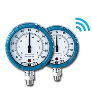
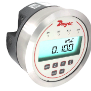
Series DH3 Digihelic® Differential Pressure Controller
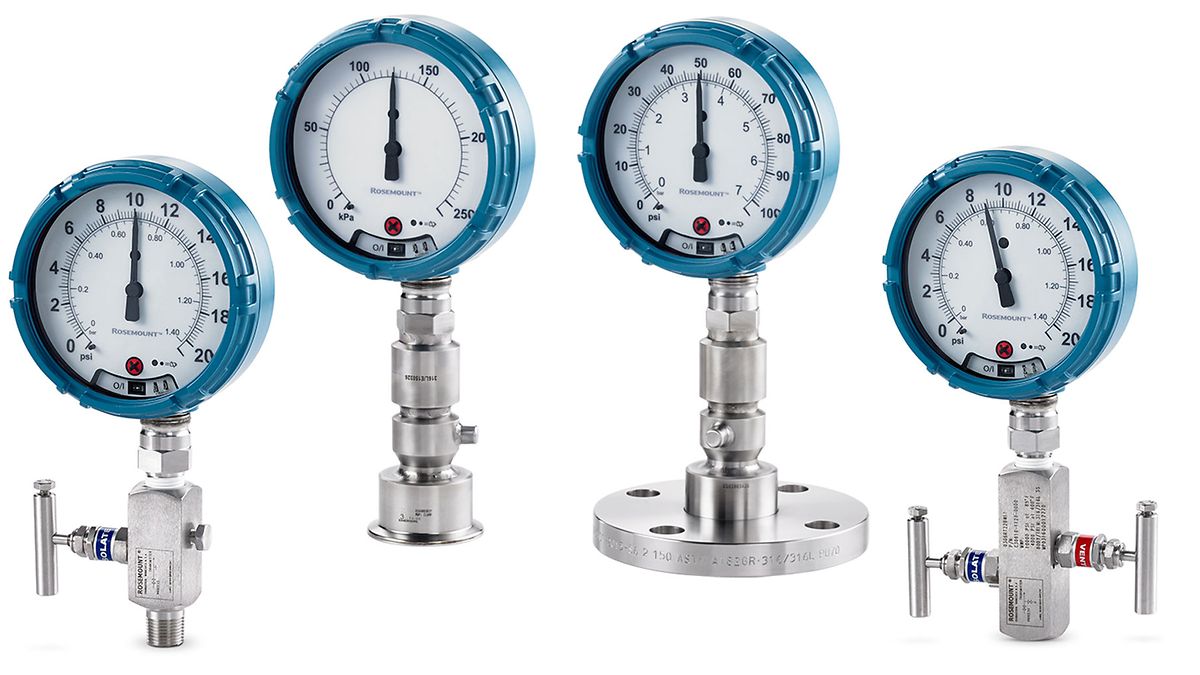
Digital indicators are for the difference between two pressures. The Gages and Switches are ideal for pressure, velocity, flow applications, and single pressure. The Series DH3 Digihelic® Differential Pressure Controller is a 3-in-1 instrument possessing a digital display gage, control relay switches, and a transmitter with current output all packed in the popular Photohelic® gage style housing.
Combining these 3 features allows the reduction of several instruments with one product, saving inventory, installation time and money. The Digihelic® controller is the ideal instrument for pressure, velocity and flow applications, achieving a 1% full-scale accuracy on ranges down to the extremely low 0.25″ w.c. to 2.5″ w.c. full scale. Ranges of 5″ w.c. and greater maintain 0.5% F.S. accuracy. Bi-directional ranges are also available.
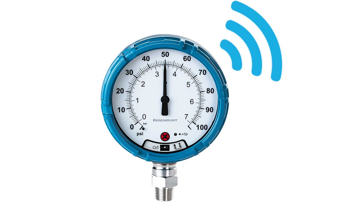
The Series DH3 Digihelic® controller allows the selection of pressure, velocity or volumetric flow operation in several commonly used engineering units. 2 SPDT control relays with adjustable dead bands are provided along with a scalable 4-20 mA process output.
Programming is easy using the menu key to access 5 simplified menus which provide access to security level; selection of pressure, velocity or flow operation; selection of engineering units; K-factor for use with flow sensors; rectangular or circular duct for inputting area in flow applications; setpoint control or setpoint and alarm operation; alarm operation as a high, low or high/low alarm; automatic or manual alarm reset; alarm delay; view peak and valley process reading; digital damping for smoothing erratic process applications; scaling the 4-20 mA process output to fit your applications range and field calibration.
Specification
Service
- Air and non-combustible, compatible gases.
Wetted Materials
- Consult factory
Housing Material
- Die-cast aluminum case and bezel
Accuracy
- ±1.5% for 0.25″ and ±0.25″ w.c. ranges. Ranges 0.5″ to 5″ w.c. and corresponding bi directional (except ±2.5″ w.c.) ±1%; All other ranges: ±0.5% @ 77°F (25°C) including hysteresis and repeatability (after 1 hour warm-up)
Stability
- < ±1% per year
Pressure Limits
- Ranges ≤ 2.5 in w.c.: 25 psi; ±2.5″, 5 in w.c.: 5 psi; 10 in w.c.: 5 psi; 25 in w.c.: 5 psi; 50 in w.c.: 5 psi; 100 in w.c.: 9 psi
Temperature Limits
- 32 to 140°F (0 to 60°C)
Compensated Temperature Limits
- 32 to 140°F (0 to 60°C)
Thermal Effects
- 0.020%/°F (0.036/°C) from 77°F (25°C). For 0.25″ and ±0.25″ w.c. ranges: ±0.03%/°F (±0.054%/°C)
Power Requirements
- 12 to 28 VDC, 12 to 28 VAC 50 to 400 Hz
Power Consumption
- 3 VA max
Output Signal
- 4 to 20 mA DC into 900 Ω max
Zero & Span Adjustments
- Accessible via menus
Response Time
- 250 ms (damping set to 1)
Display
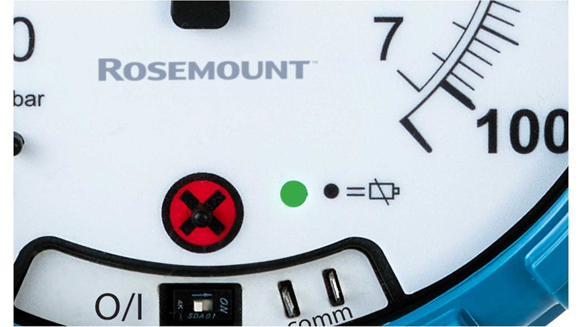
- Backlit 4 digit LCD 0.4″ height LED indicators for set point and alarm status
Electrical Connections
- 15 pin male high-density D-sub connection. 18″ (46 cm) cable with 10 conductors included
Process Connections
- 1/8″ female NPT. Side or back connections
Mounting Orientation
- Mount unit in vertical plane
Size
- 5″ (127 mm) OD x 3-1/8″ (79.38 mm)
Weight
- 1.75 lb (794 g)
Agency Approvals
- CE
Switch Type
- 2 SPDT relays
Electrical Rating
- 1 A @ 30 VAC/VDC
SetPoint Adjustment
- Adjustable via keypad on the face