Bosch Rexroth Gerotor pump

Bosch Rexroth Gerotor pump

Bosch Rexroth Gerotor pump

Bosch Rexroth Gerotor pump is hydraulic pumps with fixed displacement for low-pressure requirements. It is typically employed in combination with other Rexroth pumps.

Via the driving disk, the shaft drives the inner rotor in the direction of rotation shown. The inner rotor meshes with the outer rotor and causes the same to rotate as well. The tooth clearances opening in the suction area (S) prime the hydraulic fluid.

The suction and pressure area are separated on the opposite side of the meshing area (Z) by a radial gap (R) created by the tooth profile of the outer and the inner rotor sliding against each other. Within the pressure area (P) the hydraulic fluid is pumped into the pressure port as the chambers become.

Properties

The gearing with cycloid contour is characterized by a large meshing length. Filling zone and displacement area cover a large rotation angle. This results in low flow pulsation and thus very low operating noise. The shaft and the displacer are supported by a slide bearing and work in a wear-free manner when used as intended. Gerotor pumps PGZ are self-priming.

Construction

  • Hydraulic pumps of the PGZ type are Gerotor pumps with fixed displacement. They mainly consist of:
  • Flange housing (1)
  • shaft (2)
  • the displacer elements inner rotor (3)
  • outer rotor (4)
  • as well as driving disk (5)
  • cover (6)

Materials used

  • Flange housing (1): Aluminum
  • Shaft (2), inner rotor (3), outer rotor (4), and driving disk (5): Steel
  • Cover (6): Cast iron

Application

  • Cooling
  • filtration or lubrication circuits at low pressures in industrial or mobile applications
  • plastics processing machines
  • machine tools
  • presses and wind turbines

Features

  • Low-pressure pump with fixed displacement
  • Very low operating noise
  • Suitable for wide viscosity and speed ranges
  • Very good suction behavior
  • Flexible combination possibilities with Rexroth axial piston, internal gear, and vane pumps

Technical data

Type

  • Gerotor pump

Line connection

  • Flange connection

Shaft load

  • Radial and axial forces cannot be transmitted

Direction of rotation

  • Clockwise

Frame size

  • 4, 5

Size

  • 20… 140

Maximum operating

  • pressure 15 bar

Maximum displacement

  • 136.3 cm³

Data Sheet

Pneumatic system

Pneumatic system

Pneumatic system

A Pneumatic system is a system that uses compressed air to transmit and control energy. Pneumatic systems are used in controlling train doors, automatic production lines, mechanical clamps, etc.

Compressed air pneumatic systems require methods of safe and precise control of the actuators unique to their accouterment. Although the medium is fluid, just as hydraulic or process water systems, the execution of control is different in many ways than with a liquid. What is shared in the conduction of any fluid power medium is the need for valves to control force, velocity, and direction of movement.

Application of Pneumatic Valve

1-Air preparation

Pressure relief valves will control pressure at their inlet port by exhausting pressure to atmosphere. Relief valves are typically used only in receivers or air storage devices, such as accumulators, as a means to prevent excessive pressurization. As such, relief valves are often called safety valves and are not typically appropriate for use anywhere but the air preparation stage.

Pressure regulators in pneumatic systems limit pressure downstream of the unit by blocking pressure upstream at the inlet. Regulators are used in the air preparation stage, as well as in control of cylinders and motors. The letter R in the acronym FRL stands for the regulator, which is installed downstream of the receiver tank, but before the circuit, they are regulating pressure for.

2-Flow controls

Flow controls Also common in pneumatic systems are valves to control flow. There are fewer available types of flow valves compared to pressure or directional valves, but most circuits apply them to make for easy adjustment to the cylinder or motor velocity. Controlling velocity in pneumatic systems is more complex than in a hydraulic system because the pressure differential between the work ports of a cylinder plays a larger part.

Flow control valves for pneumatic systems are quite simple, usually available in two configurations used in two different ways. One configuration is merely a variable restriction, with a screw or knob adjustment to open and close a variable orifice, which is also often referred to as a needle or choke valve. The other type introduces a check valve, which allows free flow in one direction, and restriction in the opposing direction. For whatever reason, this valve has hijacked the name flow control all for itself.

Type of Pneumatic Valve

Two Way Valves

Two-way valves turn the air on and off in applications such as shop air, branch airlines, supply pressure to systems, and supply air to tools, motors, and similar equipment. Two-way valves can also be used as vent valves.

Three-way Valves

Three-way valves are the same as 2-way valves with the addition of a third port for exhausting downstream air. Three-way valves are available in normally open or normally closed operating configurations. These valves are used to control single acting or spring return cylinders and any load which must be pressurized and alternately exhausted. These valves can also pilot other air operated valves.

Four-Way Valves

Four-way valves use two 3-way valve functions operated at the same time, one normally closed and one normally open. These valves have two outlet ports that alternate between being pressurized and exhausted. Four-way valves are used to operate double acting air cylinders, control bi-directional air motors and in air circuitry. Also, two single-acting cylinders can be operated with one 4-way valve.

The advantages of pneumatic systems

  • High effectiveness
  • High durability and reliability
  • Simple design
  • High adaptability to the harsh environment
  • Safety
  • Easy selection of speed and pressure
  • Environmental friendly
  • Economical

The disadvantages of pneumatic systems

  • Relatively low accuracy
  • Low loading
  • The processing required before use
  • Uneven moving speed
  • Noise
Types of Air Compressor

Types of Air Compressor

Types of Air Compressor

A compressor increases the pressure of a gas. It reduces the volume of the gas and increases its density without turning that gas into a liquid. Compressors can do this in a number of ways.

However, the commonality between all compressors is the fact that they all use some sort of fuel, such as gasoline or electricity, to power whatever compression method they use.

Also, because the compressor increases the pressure on the gas, it increases the temperature of the gas. Many other types of compressors are used for various chemicals and fuels that require compression.

There are three popular Types Air Compressor :

  1. Reciprocating compressor
  2. Screw compressor
  3. Centrifugal compressor

They are often some of the most critical and expensive systems at a production facility and deserve special attention. Gas transmission pipelines, petrochemical plants, refineries, and many other industries all depend on this type of equipment.

Due to many factors, including but not limited to the quality of the initial specification/design, adequacy of maintenance practices and operational factors, industrial facilities can expect widely varying lifecycle costs and reliability from their own installations.

Various compressors are found in almost every industrial facility. Types of gases compressed include the following:

  • Air for compressed tool and instrument air systems
  • Hydrogen, oxygen, etc. for chemical processing
  • Light hydrocarbon fractions in refining
  • Various gases for storage or transmission
  • Other applications

There are two primary classifications of industrial compressors: intermittent flow (positive displacement), including reciprocating and rotary types; and continuous flow, including centrifugal and axial flow types.

Reciprocating compressor

A reciprocating compressor is a positive-displacement machine that uses a piston to compress a gas and deliver it at high pressure.

Reciprocating compressors are typically used where high compression ratios (ratio of discharge to suction pressures) are required per stage without high flow rates, and the process fluid is relatively dry.

Wet gas compressors tend to be centrifugal types. High flow, low compression ratio applications are best served by axial flow compressors. Rotary types are primarily specified in compressed air applications, though other types of compressors are also found in air service.


Screw Compressor

A screw compressor is a type of gas compressor that works on a rotary-type positive-displacement mechanism. A rotary screw compressor is commonly used to replace piston compressors wherein a large volume of high-pressure air is needed, either in large industries or to operate high power air tools. Oil-injected screw compressors are ideal for various industries and assembly production. With a capacity ranging from 7.5 KW to 37 KW, Mark Compressors provide you the best range of compressors. They have a simple LCD display control system, user-friendly design, uncompromised quality, and durability, and they even guarantee lasting performance. An oil-injected screw compressor can be used in the following industries,

  • Wastewater Treatment
  • Rubber and Plastics
  • Automotive
  • Apparel
  • Agriculture
  • Power Generation
  • Petroleum
  • General Manufacturing & many more.

Centrifugal Compressor

A centrifugal compressor is a type of dynamic compressor, or turbocompressor, with a radial design. Unlike displacement compressors that work at a constant flow, dynamic compressors work at constant pressure and the performance is affected by external conditions such as changes in inlet temperatures.

Air is drawn into the center of a rotating impeller with radial blades and is pushed toward the center by centrifugal force. This radial movement of air results in a pressure rise and the generation of kinetic energy. Before the air is led into the center of the impeller, the kinetic energy is also converted into pressure by passing through a diffuser and volute.

Each stage takes up a part of the overall pressure rise of the compressor unit. Depending on the pressure required for the application, a number of stages can be arranged in a series to achieve a higher pressure. This type of multi-stage application is often used in the oil and gas and process industries. Alternately, in wastewater treatment plants, low pressure, single-stage applications are used to achieve the desired pressure ratio.

In modern configurations of centrifugal air compressors, ultra-high speed electric motors are used to drive the impellers. This results in a compact compressor without a gearbox and associated oil-lubrication system, thus making it oil-free and appropriate for applications that require 100 percent oil-free air.

Positive Displacement Compressor

Positive Displacement Compressor

Positive Displacement Compressor

An air compressor is a device which sucks the atmospheric air and pressurizes it and to a higher pressure and gives it to the system. Compressors can be classified as

  1. Positive displacement
  2. Dynamic displacement

difference between positive displacement compressors and dynamic compressors

A positive displacement compressor, compress the air by forcing air into a compression chamber and by decreasing its volume

A dynamic displacement compressor compresses the air by imparting the kinetic energy of the rotating parts to the air. Centrifugal and axial compressors are dynamic compressors.

The basic one-line difference between positive displacement compressor (PDC) and dynamic compressor (DC) lies in the fact of how they apply the pressure on a fluid. In PDC a mechanical linkage reduces the volume of fluid physically to increase the pressure whereas in DC the fluid is provided some velocity which undergoes a diffuser resulting in the increase in pressure.

An easy way to memorize the fact is in the name itself. Positive displacement compressor means a system which compresses the air by the displacement of a mechanical linkage reducing the volume (since the reduction in volume due to a piston in thermodynamics is considered as a positive displacement of the piston). The dynamic compressor brings out a change in the velocity of the fluid eventually resulting as the rise in pressure.

Types of positive displacement compressor
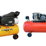
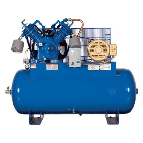
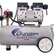
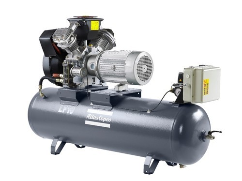
Piston Compressors

The piston compressor is the oldest and most common type of industrial compressor. It’s available in single-acting or double-acting, oil-lubricated or oil-free variants, with various numbers of cylinders in different configurations.

Oil-free piston compressors have piston rings made of polytetrafluoroethylene (PTFE) or carbon. Alternatively, the piston and cylinder wall can be profiled as on labyrinth compressors. Larger machines are equipped with a crosshead and seals on the gudgeon pins, and a ventilated intermediate piece to prevent oil from being transferred from the crankcase into the compression chamber. Smaller compressors often have a crankcase with bearings that are permanently sealed.

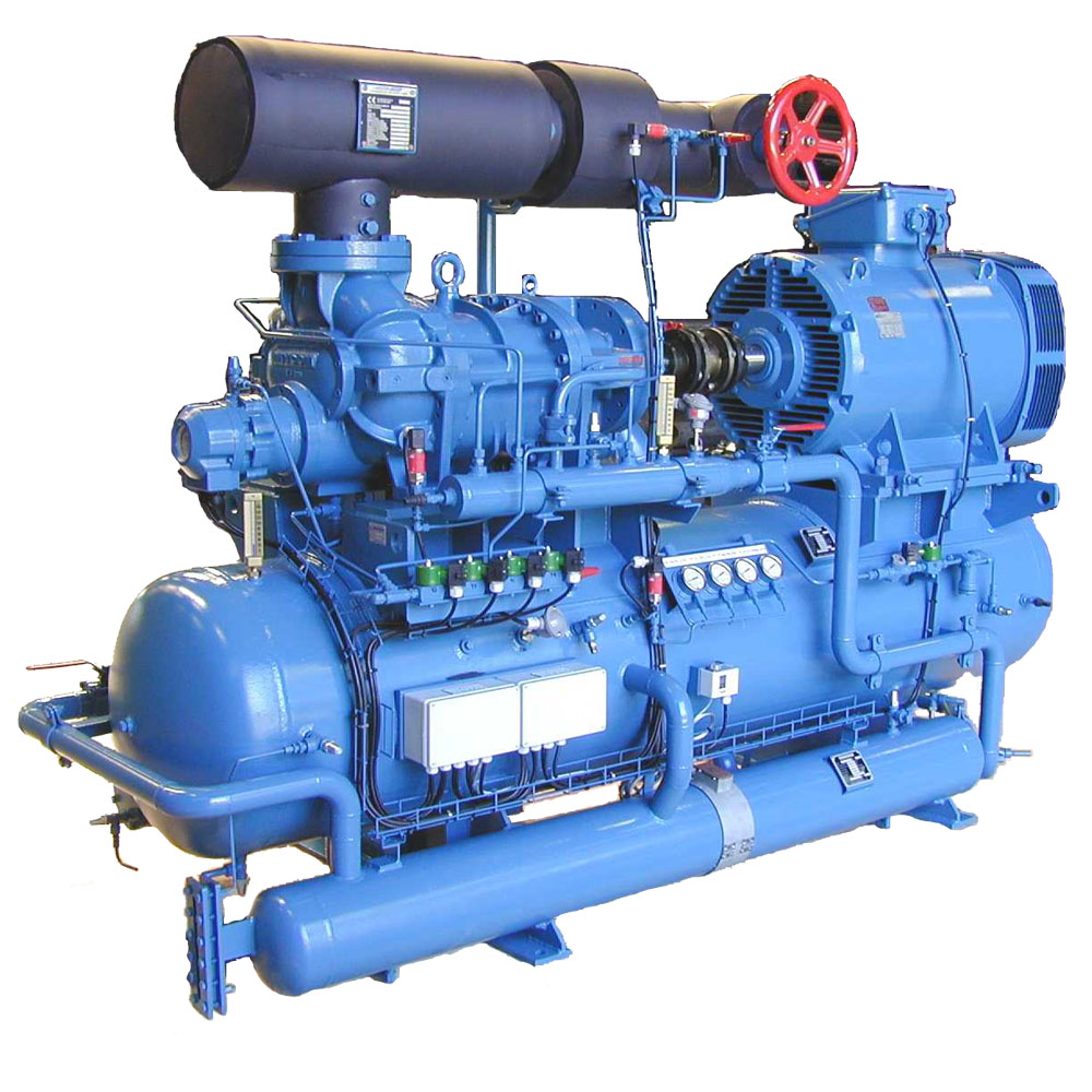
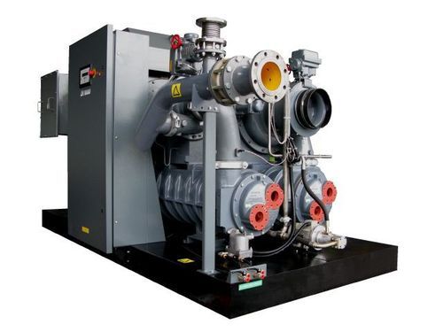
Rotary Screw Compressors 

Developed in the 1930s, rotating displacement compressors in twin screw form have two main parts — the male and female rotors, which rotate in opposite directions while the volume between them and the housing decreases. Each screw element has a fixed, built-in pressure ratio that is dependent on its length, the pitch of the screw and the form of the discharge port. To attain maximum efficiency, the built-in pressure ratio must be adapted to the required working pressure.

Modern oil-free screw compressors have asymmetric screw profiles that reduce internal leakage and improve energy efficiency. Their external gears are most often used to synchronize the position of the counter-rotating rotors. Because the rotors never come in contact with one another, no lubrication is required in the compression chamber and the compressed air produced is completely oil-free.

Liquid-injected screw compressors use liquid lubrication in their compression chamber and often with their compressor bearings as well. The liquid cools and lubricates the compressor element’s moving parts, which cools the air being compressed and reduces the return leakage to the inlet. Today, oil is the most commonly used liquid due to its good lubricating and sealing properties. Other liquids used include water.
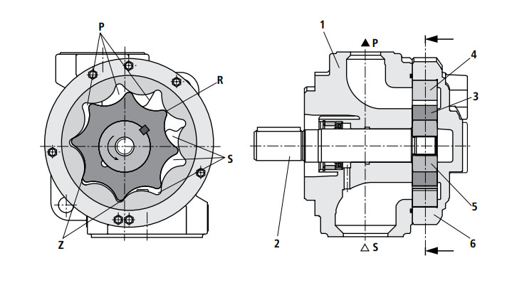
Tooth Compressors

Tooth compressors contain two rotors that rotate in opposite directions inside a compression chamber. Its compression process consists of intake, compression and outlet phases. During the intake phase, air is drawn into the compression chamber until the rotors block the inlet.

The air is then compressed in the compression chamber, which gets smaller as the rotors rotate during the compression phase. In its final phase, the outlet port is blocked during compression by one of the rotors while the inlet is open to draw in new air into the opposite section of the compression chamber.
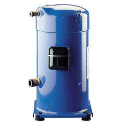
Scroll Compressors 

A scroll compressor is usually a type of oil-free orbiting displacement compressor, which compresses a specific amount of air into a continuously decreasing volume. The compressor element consists of a stator spiral fixed in a housing and motor-driven eccentric, orbiting spiral.

The spirals are mounted with 180° phase displacement to form air pockets with a gradually varying volume, which provides the scroll elements with radial stability. When the orbiting spiral moves, air is drawn in and captured in one of the air pockets, where it is gradually compressed as it moves toward the center.
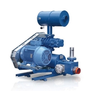


Vane Compressors 

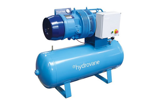
Most vane compressors are oil-lubricated and operate using the same principle as many compressed air expansion motors. A rotor with radial, movable blade-shaped vanes is eccentrically mounted in a stator housing.

When it rotates, the vanes are pressed against the stator walls by centrifugal force. Air is drawn in while the distance between the rotor and stator increases. The air is captured in the different compressor pockets, and decreases in volume with rotation and is later discharged when the vanes pass the outlet port.
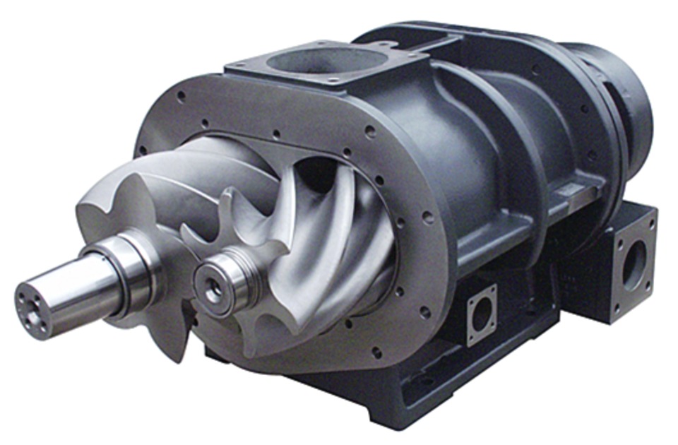
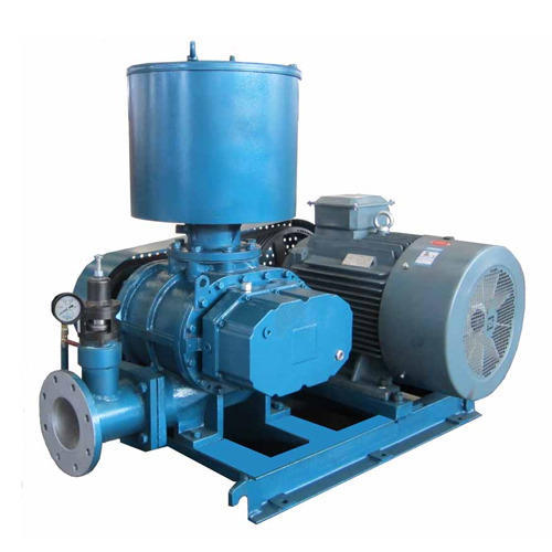


Roots Blowers

A Roots blower is a valve-less displacement compressor without internal compression. When the compression chamber comes in contact with the outlet port, compressed air flows back into the housing from the pressure side.

Subsequently, further compression takes place when the volume of the compression chamber further decreases with continued rotation. Accordingly, compression takes place against full counter-pressure, which results in low efficiency and a high noise level. Roots blowers are frequently used as vacuum pumps and for pneumatic conveyance in low pressure applications.

Air Compressor

Air Compressor

Air Compressor

An Air Compressor is a device that converts power (using an electric motor, diesel or gasoline engine, etc.) into potential energy stored in pressurized air (i.e., compressed air).

By one of several methods, an air compressor forces more and more air into a storage tank, increasing the pressure. When tank pressure reaches its upper limit the air compressor shuts off.

The compressed air, then, is held in the tank until called into use. The energy contained in the compressed air can be used for a variety of applications, utilizing the kinetic energy of the air as it is released and the tank depressurizes.

When tank pressure reaches its lower limit, the air compressor turns on again and re-pressurizes the tank.

There are numerous methods of air compression, divided into either positive-displacement or negative-displacement types.

When air is compressed, it is under pressure greater than that of the normal atmospheric pressure and it characteristically attempts to return to its normal state.

Since energy is required to compress the air, energy is released as the air expands and returns to atmospheric pressure. Air compressors were designed to compress air to higher pressures and harness this potential energy source.

Unlike other sources of power, no conversion from another form of energy such as heat is involved at the point of application. Compressed air or pneumatic devices are therefore characterized by a high power-to-weight or power-to-volume ratio.

Application of Compressor

Air compressors are found in a wide range of environments for an even wider range of uses. You’ll see gas stations offering compressed air to inflate your vehicle’s tires and your tire shop using compressed air with an air tool to remove your tires.

You may have seen small desktop air compressors used with an airbrush or a trailer-style gas-powered air compressor at a construction site powering jackhammers and concrete compactors.

In fact, you’ve likely been around many different kinds of air compressors and didn’t even know it — they may be hidden away in your refrigerator or the HVAC system at your local arena.

  • Blowing up balloons or inflatable products
  • Adding air to tires on bikes and on vehicles
  • Cleaning crevices and tight spaces on equipment or other durable items with directed air pressure
  • Painting with an airbrush for small precision projects or on larger surfaces like bikes and the body of vehicles and recreational vehicles
  • Using various pneumatic tools for home projects
  • Painting vehicles in an auto body shop
  • Sanding in an auto body shop or in woodworking
  • Making snow at ski hills or for entertainment uses
  • Using pneumatic nail guns for roofing
  • Providing dental and medical services
  • Using pneumatic drills and hammers on construction sites
  • Powering various air tools in an automotive repair shop
  • Using an air blowgun to clean machinery
  • Sandblasting in a machine shop and manufacturing facilities
  • Moving feed and grain to and from silos with conveyors
  • Glasshouse ventilation systems
  • Spraying crops
  • Powering dairy machines
  • Operating pneumatic material handling equipment
  • …..

Compressor Types

Dynamic

  1. Axial
  2. Centrifugal

Positive Displacement

1.Rotary

  • Screw
  • Blower

2.Reciprocating

  • Single Acting
  • Double Acting

References: