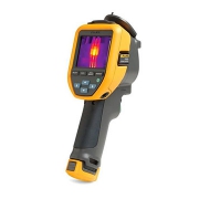
Fluke TiS20+ Thermal Imaging Camera
Fluke TiS20+ Thermal Imaging Camera
Temperature can be a sign of trouble ahead. With Fluke Thermal Imaging Camera you can detect issues before they become problems. Designed for everyday use, in the toughest industrial environments, Fluke offers infrared cameras for a wide range of applications.
What are Thermal Imaging Cameras?
Thermal imaging cameras are handheld electronic devices with an integrated visual display, designed for detecting heat energy.
The key component of a thermal camera is a heat sensor attached to a special type of lens, which is then adapted to work alongside standard image-capture technologies. This allows engineers to quickly identify regions of excessive temperature or sources of wasted heat energy, such as overheating components or potential thermal insulation gaps in building inspection.
Visible light forms only a small part of the electromagnetic spectrum, and the only part we can actually see. When pointed at an object or area, the sensor on a thermal detection camera allows the user to view the otherwise invisible infrared spectrum, which exists at wavelengths between visible light and microwaves.
This is often rendered as a color map in modern IR cameras, although black-and-white displays are still preferred for certain applications due to their reduced visual ‘busyness’ and improved capture of fine detail.
On a color thermographic display, warmer components or regions will show up as reds, oranges, and yellows, while cooler parts will typically be shown as purples and blues (green usually indicates areas that are roughly at room temperature). Because they measure infrared radiation, and not visible light, thermal cameras are also useful for identifying heat sources in very dark or otherwise obscured environments.
How thermal imaging cameras work?
An infrared, IR or thermal imaging camera works by detecting and measuring the infrared radiation emanating from objects – in other words, their heat signature.
In order to do so, the camera must first be fitted with a lens that allows IR frequencies to pass through, focusing them on to a special sensor array which can, in turn, detect and read them.
The sensor array is constructed as a grid of pixels, each of which reacts to the infrared wavelengths hitting it by converting them into an electronic signal. Those signals are then sent to a processor within the main body of the camera, which converts them using algorithms into a color map of different temperature values. It’s this map which is sent on to be rendered by the display screen.
Many types of thermal imaging cameras will also include a standard shooting mode that works with the visible light spectrum, much like any other point-and-click digital camera. This allows for easy comparison of two identical shots – one in IR and one in normal mode – to help quickly identify specific problem areas once the user steps out from behind the lens.
Specifications
Infrared resolution
- 120 x 90 (10,800 pixels)
IFOV (spatial resolution)
- 7.6 mRad, D:S 130:1
Field of view
- 50° H x 38° V
Minimum focus distance
- 50cm (20 inches)
Level and span
- Smooth auto and manual scaling
Display
- 3.5″ LCD touchscreen (landscape)
Display resolution
- 320 x 240 LCD
Thermal sensitivity (NETD)
- 60 mK
Frame rate
- 9 Hz
Batteries (field-replaceable, rechargeable)
- Lithium-ion smart battery pack with five-segment LED display to show charge level
Battery life
- ≥ 5 hours continuous (without WiFi)
Battery charging time
- 2.5 hours to full charge
Temperature measurement range (not calibrated below 0 °C)
- -20 °C to 150 °C (-4°F to 302°F)
Accuracy
- Target temp at or over 0 °C: Accuracy: ± 2 °C or ± 2 % at 25 °C, whichever is the greater.
Weight
- 0.72 kg (1.6 lb)
Size (H x W x L)
- 26.7 cm x 10.1 cm x 14.5 cm (10.5 in x 4.0 in x 5.7 in)
Enclosure rating
- IP54 (protected against dust, limited ingress; protection against water spray from all directions)
Data Sheet
![]()

 Special Features