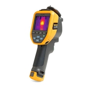
Fluke TiS20+ Thermal Imaging Camera

Fluke TiS20+ Thermal Imaging Camera

Temperature can be a sign of trouble ahead. With Fluke Thermal Imaging Camera you can detect issues before they become problems. Designed for everyday use, in the toughest industrial environments, Fluke offers infrared cameras for a wide range of applications.

What are Thermal Imaging Cameras?

Thermal imaging cameras are handheld electronic devices with an integrated visual display, designed for detecting heat energy.

The key component of a thermal camera is a heat sensor attached to a special type of lens, which is then adapted to work alongside standard image-capture technologies. This allows engineers to quickly identify regions of excessive temperature or sources of wasted heat energy, such as overheating components or potential thermal insulation gaps in building inspection.

Visible light forms only a small part of the electromagnetic spectrum, and the only part we can actually see. When pointed at an object or area, the sensor on a thermal detection camera allows the user to view the otherwise invisible infrared spectrum, which exists at wavelengths between visible light and microwaves.

This is often rendered as a color map in modern IR cameras, although black-and-white displays are still preferred for certain applications due to their reduced visual ‘busyness’ and improved capture of fine detail.

On a color thermographic display, warmer components or regions will show up as reds, oranges, and yellows, while cooler parts will typically be shown as purples and blues (green usually indicates areas that are roughly at room temperature). Because they measure infrared radiation, and not visible light, thermal cameras are also useful for identifying heat sources in very dark or otherwise obscured environments.

How thermal imaging cameras work?

An infrared, IR or thermal imaging camera works by detecting and measuring the infrared radiation emanating from objects – in other words, their heat signature.

In order to do so, the camera must first be fitted with a lens that allows IR frequencies to pass through, focusing them on to a special sensor array which can, in turn, detect and read them.

The sensor array is constructed as a grid of pixels, each of which reacts to the infrared wavelengths hitting it by converting them into an electronic signal. Those signals are then sent to a processor within the main body of the camera, which converts them using algorithms into a color map of different temperature values. It’s this map which is sent on to be rendered by the display screen.

Many types of thermal imaging cameras will also include a standard shooting mode that works with the visible light spectrum, much like any other point-and-click digital camera. This allows for easy comparison of two identical shots – one in IR and one in normal mode – to help quickly identify specific problem areas once the user steps out from behind the lens.

Specifications

Infrared resolution

  • 120 x 90 (10,800 pixels)

IFOV (spatial resolution)

  • 7.6 mRad, D:S 130:1

Field of view

  • 50° H x 38° V

Minimum focus distance

  • 50cm (20 inches)

Level and span

  • Smooth auto and manual scaling

Display

  • 3.5″ LCD touchscreen (landscape)

Display resolution

  • 320 x 240 LCD

Thermal sensitivity (NETD)

  • 60 mK

Frame rate

  • 9 Hz

Batteries (field-replaceable, rechargeable)

  • Lithium-ion smart battery pack with five-segment LED display to show charge level

Battery life

  • ≥ 5 hours continuous (without WiFi)

Battery charging time

  • 2.5 hours to full charge

Temperature measurement range (not calibrated below 0 °C)

  • -20 °C to 150 °C (-4°F to 302°F)

Accuracy

  • Target temp at or over 0 °C: Accuracy: ± 2 °C or ± 2 % at 25 °C, whichever is the greater.

Weight

  • 0.72 kg (1.6 lb)

Size (H x W x L)

  • 26.7 cm x 10.1 cm x 14.5 cm (10.5 in x 4.0 in x 5.7 in)

Enclosure rating

  • IP54 (protected against dust, limited ingress; protection against water spray from all directions)

Data Sheet

References

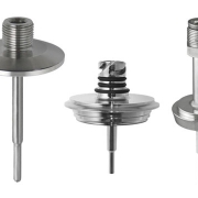
hygienic RTD thermometer

Endress+Houser hygienic RTD thermometer

iTHERM TM411 Endress+Houser hygienic RTD thermometer

Endress+Houser hygienic RTD thermometer has been designed to meet the requirements of the Food & Beverages and Life Sciences industries and complies with the highest quality standards. It offers a variety of versions within a clearly segmented standard product. The result: Time and cost savings by simple and fast product selection.

It offers many technical innovations: iTHERM QuickSens, StrongSens or QuickNeck. This leads to a distinctive reduction in maintenance costs, improved product quality, process efficiency, and safety.

What is Hygienic?

Hygiene is a central topic when it comes to industrial manufacturing and processing. Good hygiene conditions provide the best foundation for human health and a clean environment. The legal provisions, ordinances, and certifications created for this purpose should therefore not be conceived as an inconvenient obligation; instead, they give us a great chance to improve the quality of our own products and guarantee a maximum of consumer protection.

In numerous areas of industry, professional disinfection is, particularly of crucial importance. It often has a very immediate impact on the quality of the products manufactured or those subject to further processing. The effectiveness of the actions taken to reduce contaminations or hazards usually relies on the perfect interaction of disinfection products, disinfection technology, and consulting services.

Technical Specification of iTHERM TM411 Endress+Houser RTD thermometer

  • Specially designed for use in hygienic and aseptic applications in the Food & Beverages and Life Sciences industries
  • Measuring range: –200 to +600 °C (–328 to +1112 °F)
  • Pressure range up to 50 bar (725 psi)
  • Protection class: up to IP69K
  • Head transmitter
  •  All Endress+Hauser transmitters are available with enhanced accuracy and reliability compared to directly wired sensors. Easy customizing by choosing one of the following outputs and communication protocols:
  • Analog output 4 to 20 mA, HART®
  • PROFIBUS® PA, FOUNDATION Fieldbus™

Benefits

  • User-friendly and reliable from product selection to maintenance
  • globally unique, automated production. Full traceability and consistently high product quality for reliable measured values
  • fastest response times (t90s: 1.5 s) for optimum process control
  • unsurpassed vibration resistance (> 60g) for ultimate plant safety
  • iTHERM QuickNeck – cost and time savings thanks to simple, tool-free recalibration
  • 316L terminal head for easier handling and lower installation and maintenance costs, and with a highest IP69K rating
  • International certification: explosion protection e.g. ATEX/IECEx and in compliance with hygiene standards according to 3-A®, EHEDG, ASME BPE, FDA, TSE Certificate of Suitability

Technical Data

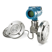
Rosemount™ 3051SAL Level Transmitter

Rosemount 3051SAL Level Transmitter

Rosemount 3051SAL Level Transmitter

Make reliable pressure measurements in extreme conditions with the Rosemount 3051SAL Level Transmitter, a best-in-class solution that offers enhanced capabilities for pressurized and vented tank level measurements. This transmitter is safety certified and engineered with advanced diagnostics for increased insight. Designed to allow direct mounting, remote mounting, balanced systems and Tuned-System™ assemblies, this device can meet a variety of demands and process requirements for level applications.

Features of Rosemount 3051S DP Level Technology

1- ERS System

Electronic Remote Sensor (ERS™) Systems provide DP Level measurements by calculating differential pressure from individual pressure readings. This solution eliminates the need for long capillaries and heat tracing, reducing response time by up to 90%. The sensor system is synchronized for DP calculation, easily connects with cable, and can be independently installed and serviced for simple installation and maintenance.

2- Thermal Range Expander

Thermal Range Expander enables pressure and level measurements in high-temperature processes. This seal system uses two different fill fluids, extending the operating range of the transmitter from temperatures ranging from -75 °C (-103 °F) to 410 °C (770 °F). With an improved response time of up to 46%, thermal range expanders simplify installation and reduce cost by eliminating impulse piping and heat tracing.

3- Wireless Technology

With Wireless Technology, you can add new measurement points easily and cost-effectively in many areas of the plant including those that were previously inaccessible. This information allows you to better optimize your level measurements and reduce personnel exposure to hazardous environments. Get coverage over larger areas with long-range communication options up to 1 km (2/3 mi) between devices.

4- Diaphragm Seal System

The Diaphragm Seal System protects transmitters from hot, cold, corrosive, erosive or viscous processes. Seals are available with differential, gauge and absolute pressure transmitters. Advanced welding and assembly techniques prevent weld corrosion and improve seal strength to deliver reliability and performance in the toughest applications.

5- Expanded Capabilities

The Rosemount 3051S enhanced features offer a scaled process variable, enabling this device to convert pressure units to customized, user-defined units. Process pressure or temperature alerts can also be configured as well as alerts of abnormal process conditions. In addition, the 3051S features remote mount LCD display capabilities, allowing direct mounting of the device while keeping the local display in a convenient location.

6- Seal System Construction

1- Universal Connection

  • Welded capillary/instrument connection eliminates leaks and improves reliability

2- Advanced Weld Techniques

  • Engineered to prevent weld corrosion
  • Improves seal reliability

3- Backup Diaphragm Pattern

  • Matches pattern of diaphragm
  • Helps diaphragm maintain original form
  • Reduces oil volume for improved performance

4-  Recessed Diaphragm

  • Protects diaphragm from installation damage
  • Minimize gasket induced errors
  • Protects diaphragm from installation damage
  • Prevents zero offset pressure on the diaphragm from the off-centered gasket

Specifications

Max. Operating Pressure

  • Up to 10,000psi (689.48 bar)

Process Temperature Range

  • Based on fill fluid – Maximum 770°F (410°C), Minimum -157°F (-105°C)

Communication Protocol

  • 4-20 mA HART®
  • WirelessHART®
  • FOUNDATION™ Fieldbus

Seal System Type

  • Direct Mount
  • Remote Mount
  • Tuned-System
  • Balanced System

Transmitter Connection

  • Welded-Repairable
  • All Welded

Process Connection

  • Flanged: ANSI/ASME, EN/DIN, GOST, & JIS
  • Threaded: NPT, DIN, ISO
  • Hygienic

Process Wetted Material

  • 316L SST
  • Alloy C-276
  • Alloy 400
  • Tantalum
  • Gold-plated Alloy 400
  • Gold-plated 316L SST

Diagnostics

  • Basic Diagnostics
  • Loop Integrity
  • Process Intelligence
  • Plugged Impulse Line

Certifications/Approvals

  • SIL 2/3 certified to IEC 61508 by an independent 3rd party
  • NACE®
  • 3A
  • hazardous location

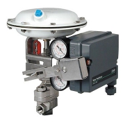
Fisher 3661 Electro-Pneumatic Positioner

Fisher 3661 Electro-Pneumatic Positioner

Fisher 3661 Electro-Pneumatic Positioner

Fisher Electro-Pneumatic Positioner is used with various actuators on sliding-stem valves for throttling applications. These rugged positioners provide a valve position proportional to a pneumatic input or a standard milliampere DC input signal received from a control device.

What is a Valve Positioner?

As a common control valve accessory, the valve positioner delivers pressurized air to the valve actuator so that the position of the valve stem or shaft corresponds to the setpoint from the control system. Valve positioners are typically pneumatic or analog I/P and are used when a valve requires throttling action. They require position feedback from the valve stem or shaft and deliver pneumatic pressure to the actuator to open and close the valve

Pneumatic Valve Positioners

Legacy processing units may use pneumatic pressure signaling as the control setpoint to the control valves. In a common pneumatic positioner design, a pneumatic input signal is received from a control device and modulates the supply pressure to the control valve actuator, providing an accurate valve stem or shaft position that is proportional to the pneumatic input signal.

Analog I/P Valve Positioners

Most modern processing units use a 4 to 20 mA DC signal to modulate control valves. This introduces electronics into the positioner design and requires that the positioner convert the electronic current signal into a pneumatic pressure signal (current-to-pneumatic or I/P). In a typical analog I/P positioner, the converter receives a DC input signal and provides a proportional pneumatic output signal through a nozzle/flapper arrangement. The pneumatic output signal provides the input signal to the pneumatic positioner.

Features

  • Positioner design provides accurate, fast-responding instruments able to withstand the vibrations of most plant environments. Low steady-state air consumption contributes to efficient operation.
  • Easily adjustable gain and damping adjustments fine-tune the positioner stability to specific application requirements.
  • The positioner accepts a standard milliampere DC input signal from a control device. This positioner provides split range capabilities and adjustable zero and spans.
  • Most of the parts for 3661 positioners are interchangeable; requiring fewer spare parts to support these positioners.
  • The case and cover are designed to withstand mechanical vibration and rough handling.
  • Zero and span adjustments can be made with the cover in place.
  • To support diagnostic testing of valve/actuator/positioner packages with the FlowScanner™ valve diagnostic system, connectors, piping, and other hardware can be installed between the 3661 positioner and the actuator.

Fisher Electro-Pneumatic Positioner Specifications

Area Classification

  • Intrinsically Safe
  • Non-incendive
  • Dust

Certifications

  • CSA
  • FM
  • ATEX
  • IECEx
  • CUTR
  • Peso
  • KGS
  • INMETRO
  • RCM

Communication Protocol

  • 4-20mA Analog

Diagnostics

  • No

Input Signal

  • Electric

Max Outlet Pressure

  • 90 psi

Mounting Type

  • Actuator Mounted

Operating Temperature

  • Standard Temperature

Position Control

  • Modulating

Safety Certification

  • NIL

Supply Media

  • Air

Other Configurations

  • Contact your local Emerson business partner or sales office to learn about additional specifications or options for this product.

Fisher Flanged Control Valve

Fisher Flanged Control Valve

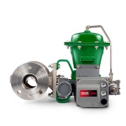
Fisher Vee-Ball™ V300 Flanged Control Valve

The Fisher Vee-Ball V300 Flanged control valve is your best choice for performance and cost-effectiveness across a broad range of applications. The precision-machined parts and pressure-balanced seal designs allow smooth, precise valve operation.

What is a Segmented Ball Valve?

A segmented ball valve is similar to a conventional ball valve, but with a contoured V-notch segment in the ball. This control valve has good rangeability, control, and shutoff capability. The V-notch ball provides positive shearing action and produces an inherent equal percentage flow characteristic. It provides non-clogging, high capacity flow control. The V-notch ball has been specially contoured to maximize capacity and enhance seal life and shutoff integrity.

Common Applications

V-notch ball control valve bodies are suited to control erosive or viscous fluids, paper stock, or other slurries containing entrained solids or fibers. The paper industry, chemical plants, sewage treatment plants, the power industry, and petroleum refineries use such valve designs.

Features

  • Flanged body design eliminates exposed line flange bolting, reduces alignment and installation time, and promotes secure valve installations and piping integrity.
  • The solid HD ball seal construction provides long service life in demanding applications.
  • Precise contouring of the Vee-Ball provides a modified equal percentage flow characteristic.
  • Materials are available for applications involving sour liquids and gases. These constructions comply with NACE MR0175-2002, MR0175-2003, MR0103, and MR0175/ISO 15156.
  • Ball seal inspection and replacement are done at the valve body inlet, without removing the actuator or disassembling the valve.
  • The one-piece valve body improves the structural integrity of the pressure boundary by eliminating leak paths that could be caused by the gaskets in the two-piece, bolted valve designs.
  • The optional ENVIRO-SEAL™ packing systems are designed with very smooth shaft surfaces and live loading to provide exceptional sealing.

Specifications

Certifications

  • SIL capable
  • ATEX
  • CUTR
  • PED
  • CRN
  • Fugitive Emission
  • NACE

Critical Service

  • Noise Abatement
  • Cavitation
  • Dirty Service
  • Erosive
  • Low Flow
  • General Service

Flow Characteristics

  • Equal Percentage

Material

  • Carbon Steel
  • Stainless
  • Duplex
  • Alloy

Operating Temperature

  • Standard Temperature

Pressure Class

  • PN
  • ASME

Process Connection Type

  • Flanged

Shutoff Class

  • Class III (FCI 70-2)
  • Class IV (FCI 70-2)
  • Class VI (FCI 70-2)

Valve Size

  • NPS 1
  • NPS 1-1/2
  • NPS 2
  • NPS 3
  • NPS 4
  • NPS 6
  • NPS 8
  • NPS 10
  • NPS 20

Data Sheet

Rising Stem Ball Valves

RISING STEM BALL VALVES Flowserve

RISING STEM BALL VALVES Flowserve

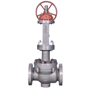
Valbart RSBV Rising Stem Ball Valves are the oil and gas industry’s choice for applications requiring a mechanically energized metal or soft seat to prevent losses from process contamination or material leakage. They are ideal for frequent cycling.

The RSBV uses a unique helix system that opens and closes the valve without rotation. The linear only operation of the stem makes it an excellent choice for frequent cycling. Each linear operation, from opening to closing and back again, is a friction-free movement between seat and ball that significantly reduces valve wear and keeps routine maintenance to a bare minimum. The outside yoke and screw, with stuffing box-type gland packing, including gland and gland flange, eliminates the need for special tools when adjusting or repacking the stem seal. Top entry convenience allows visual inspection inside the valve without removing the valve from the pipeline. The stem also has a backseat to prevent possible blowouts and repacking stem seals under pressure when the valve is fully open. A special lapping technique applied to the Stellite6® ball and seat sealing areas allows for zero seat leakage. Heavy wall thickness provides extra corrosion allowance to reduce wear and extend the valve lifetime

Industries

  • General Industry
  • Chemicals
  • Water
  • Oil & Gas
  • Power
  • Basic (Organic & Inorganic)
  • Biofuels
  • Petrochemicals
  • Waste Water
  • Agriculture
  • Upstream Exploration & Production
  • Midstream Transportation
  • Downstream Processing
  • Conventional Steam

Standards

  • API 6D/API 6FA-607/FCI 70-2
    NACE MR0175/API 598

Size Range

  • DN 25 to 600
  • NPS 1 to 24

Pressure Class Range

  • PN 10 to 320
  • Class 150 to 2500

Seating Material

  • Metal or soft

Features and Benefits

  • Extended service life and low maintenance costs due to unique helix coil stem design, which enables friction-free opening and closing
  • Improved product quality, efficiency, and safety with tightness performance up to ANSI FCI-70-2 Class VI
  • Easy in-line inspection and maintenance enabled by top-entry design
  • Reduced corrosion due to heavy wall thickness in excess to ASME/ANSI B16.34
  • Improved personnel safety from blowout-proof stem that meets international standards of API 600 and 6D

Other Features

  • Combination of a quarter-turn ball valve with a linear movement of non-rotating stem
  • Trunnion mounted design
  • Reduced or full bore
  • Single-seat (no valve body cavity)
  • Unidirectional or bidirectional
  • Metal to metal seat with stellite welding overlay (soft seat insert on request)
  • Outside screw and yoke for adjusting of stem packing
  • Blowout proof stem
  • Suitable for very high frequent cycling operations (switching valves)
  • Tight shut-off by means of application of external mechanical force and not dependent on differential pressure
  • Proper selection of materials to avoid galling and high friction
  • Protected lower trunnion against solid particles intrusion
  • Clearance control to consider high/low-temperature shrinkages
  • Self-cleaning closure member

Data Sheet

Differential Pressure Controller

Differential Pressure Controller

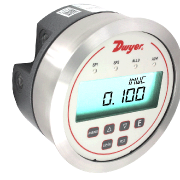
Series DH3 Digihelic® Differential Pressure Controller

Digital indicators are for the difference between two pressures. The Gages and Switches are ideal for pressure, velocity, flow applications, and single pressure. The Series DH3 Digihelic® Differential Pressure Controller is a 3-in-1 instrument possessing a digital display gage, control relay switches, and a transmitter with current output all packed in the popular Photohelic® gage style housing.

Combining these 3 features allows the reduction of several instruments with one product, saving inventory, installation time and money. The Digihelic® controller is the ideal instrument for pressure, velocity and flow applications, achieving a 1% full-scale accuracy on ranges down to the extremely low 0.25″ w.c. to 2.5″ w.c. full scale. Ranges of 5″ w.c. and greater maintain 0.5% F.S. accuracy. Bi-directional ranges are also available.

The Series DH3 Digihelic® controller allows the selection of pressure, velocity or volumetric flow operation in several commonly used engineering units. 2 SPDT control relays with adjustable dead bands are provided along with a scalable 4-20 mA process output.

Programming is easy using the menu key to access 5 simplified menus which provide access to security level; selection of pressure, velocity or flow operation; selection of engineering units; K-factor for use with flow sensors; rectangular or circular duct for inputting area in flow applications; setpoint control or setpoint and alarm operation; alarm operation as a high, low or high/low alarm; automatic or manual alarm reset; alarm delay; view peak and valley process reading; digital damping for smoothing erratic process applications; scaling the 4-20 mA process output to fit your applications range and field calibration.

Specification

Service

  • Air and non-combustible, compatible gases.

Wetted Materials

  • Consult factory

Housing Material

  • Die-cast aluminum case and bezel

Accuracy

  • ±1.5% for 0.25″ and ±0.25″ w.c. ranges. Ranges 0.5″ to 5″ w.c. and corresponding bi directional (except ±2.5″ w.c.) ±1%; All other ranges: ±0.5% @ 77°F (25°C) including hysteresis and repeatability (after 1 hour warm-up)

Stability

  • < ±1% per year

Pressure Limits

  • Ranges ≤ 2.5 in w.c.: 25 psi; ±2.5″, 5 in w.c.: 5 psi; 10 in w.c.: 5 psi; 25 in w.c.: 5 psi; 50 in w.c.: 5 psi; 100 in w.c.: 9 psi

Temperature Limits

  • 32 to 140°F (0 to 60°C)

Compensated Temperature Limits

  • 32 to 140°F (0 to 60°C)

Thermal Effects

  • 0.020%/°F (0.036/°C) from 77°F (25°C). For 0.25″ and ±0.25″ w.c. ranges: ±0.03%/°F (±0.054%/°C)

Power Requirements

  • 12 to 28 VDC, 12 to 28 VAC 50 to 400 Hz

Power Consumption

  • 3 VA max

Output Signal

  • 4 to 20 mA DC into 900 Ω max

Zero & Span Adjustments

  • Accessible via menus

Response Time

  • 250 ms (damping set to 1)

Display

  • Backlit 4 digit LCD 0.4″ height LED indicators for set point and alarm status

Electrical Connections

  • 15 pin male high-density D-sub connection. 18″ (46 cm) cable with 10 conductors included

Process Connections

  • 1/8″ female NPT. Side or back connections

Mounting Orientation

  • Mount unit in vertical plane

Size

  • 5″ (127 mm) OD x 3-1/8″ (79.38 mm)

Weight

  • 1.75 lb (794 g)

Agency Approvals

  • CE

Switch Type

  • 2 SPDT relays

Electrical Rating

  • 1 A @ 30 VAC/VDC

SetPoint Adjustment

  • Adjustable via keypad on the face
Rosemount Thermocouple

Rosemount Thermocouple Temperature Sensor

Rosemount 185 Thermocouple Temperature Sensor

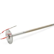
Meet the required standards of your process temperature measurements with the Rosemount 185 Thermocouple Temperature Sensor. Rosemount Thermocouple Temperature Sensor covers a range of temperatures and is engineered as type J, K or N thermocouples (IEC 584 Class 1) with or without a thermowell to meet a variety of application requirements. This flexible temperature measurement solution also offers many configurations, enclosure and connection head options, and remote or integral mounting designs.

The Rosemount DIN-Style Sensor and Thermowell have designs that provide flexible and reliable temperature measurements in process environments. Features include:

  • Temperature range of –196 to 450 °C for RTD, –40 to 1000 °C for thermocouple
  • Industry-standard sensor types, including RTD and thermocouple varieties
  • DIN-style design for easy mounting and replacement
  • Variety of enclosure and connection head options
  • Global hazardous-location approvals available
  • Calibration services available to give you insight to sensor performance
  • MID calibration options for custody transfer
  • Assemble to transmitter option

Specifications

Insulation Resistance

  • 1,000 MΩ minimum insulation resistance when measured at 500 Vdc and at room temperature

Certifications/Approvals

  • Hazardous location, see full specs for complete list of certifications

Lead Wires

  • PTFE insulated, 0.52 mm2 (20 AWG) stranded thermocouple wire, color-coded per IEC 584

Features

  • Sensor designed per IEC 584 to offer optimal performance
  • Sensor selections cover a wide range of temperatures from -40 to 1832°F (-40 to 1000°C) to meet process demands
  • Available in single element, dual element and isolated configurations with ungrounded junctions for adaptability
  • DIN-style sensor connection heads allow for quick mounting and replacement
  • Terminal block, flying leads and spring-loaded threaded adapters provide remote or integral mounting configuration
  • Adaptable design with a variety of enclosure and connection head options meets varying application requirements
  • Option for thermowell assembly delivers increased protection from corrosive environments
  • Global hazardous location approvals meet local requirements

Technical Specification

Model

0065

  • Pt 100 RTD (IEC 751) without thermowell

0185

  • Thermocouple (IEC 584 Class 1) without thermowell

Connection head

  • 2 1/2-in. NPT
  • M20 1.5

Temperature range

  • –50 to 450 °C (–58 to 842 °F)
  • –196 to 300 °C (–321 to 572 °F)
  • –40 to 750 °C (–40 to 1382 °F)
  • –40 to 1000 °C (–40 to 1832 °F)
  • –60 to 600 °C (–76 to 1112 °F)
  • –40 to 1000 °C (–40 to 1832 °F)

Material

  • 300 series stainless steel

What is Thermocouple

A thermocouple is comprised of at least two metals joined together to form two junctions. One is connected to the body whose temperature is to be measured; this is the hot or measuring junction. The other junction is connected to a body of known temperature; this is the cold or reference junction. Therefore the thermocouple measures unknown temperature of the body with reference to the known temperature of the other body.

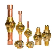
Danfoss sight glasses

Danfoss sight glasses

Danfoss sight glasses SGP is a series of sight glasses for high-pressure applications. SGP is available in versions optimized for refrigerants with mineral oil e.g. HCFC, and in versions optimized for non-flammable HFC refrigerants.

SGP for food retail refrigeration is available with flare, solder and socket connections, and with and without moisture indicators.

SGP sight glass is part of the Danfoss line components program which covers a wide range of components used in refrigeration systems.

What is Sight Glass?

a sight glass is a transparent glass tube or window installed in a tank or boiler system that allows an observer to view what is happening inside the container, ensuring optimal quality and safety. Sight glasses can also serve a number of functions aside from basic viewing, but this is the most common use.

While “sight glass” is a general, overarching term, there are also several more specific terms that are used to refer to different types of sight glasses. Some of the most common types of sight glasses are outlined below.

Applications of Sight Glass

Sight glasses find application in a broad spectrum of industries, such as:

  • Pharmaceuticals
  • Biofuels
  • Food and beverage processing
  • Utilities and energy
  • Chemical/petrochemical
  • Wastewater treatment and management
  • Boiler systems
  • Industrial burners
  • Pulp and paper processors
  • Oil and gas refineries
  • Automobiles and other transport vehicles
  • Combustion equipment

Sight glass Types

  • Circular sight glass fittings
  • Sight flow indicators
  • Metaglas sight glass windows
  • Glass tube liquid level gauge and Magnetic Level gauges
  • Rectangular sight glass fittings
  • Sanitary and hygienic equipment
  • Water Treatment Sight Glass Fittings

Features and benefits of Danfoss SGP

  • Good visibility to indicate flow conditions
  • Low leakage
  • Long service life
  • Extra safety with MWP 52 bar
  • Reliability of products ensures less leakage and long lifetime
  • Fast react indicator provides early warning to prevent excessive liquid

Data Sheet

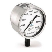
1109 Process Pressure Gauge Ashcroft

Pressure Gauge Ashcroft

1109 Process Pressure Gauge Ashcroft

A pressure gauge is a mechanical instrument designed to measure the internal pressure and/or vacuum of a vessel or system. Trerice Pressure Gauges are offered in a variety of styles, sizes, and wetted part materials to meet the demands of standard and special applications.

Most Trerice Pressure Gauges are constructed with a bourdon tube sensing element. When the sensing element is subjected to pressure, it flexes and the resulting motion is transmitted as a measurement through a mechanical movement to the dial face pointer

The Ashcroft 1109 pressure gauge is a rugged instrument and an ideal choice when an ASME gauge with a solid front stainless steel case is a requirement. This model combines elements of reliability, performance, and safety. An ideal product that serves extremely well on challenging installation points.

FEATURES of Pressure Gauge Ashcroft

  • PLUS!™ Performance dampens vibration, shock and pulsation effects
  • Solid front design with full blowout back
  • Epoxy coated system offers superior corrosion resistance
  • Rugged design

 TYPICAL USES

  • Oil and Gas
  • Offshore Oil Rigs
  • Chemical and Petrochemical Plants
  • Refineries
  • Waterblasting / Water Jetting Equipment
  • Specialized OEM Equipment

SPECIFICATIONS

Accuracy

  • ±0.5% of span (ASME B40.100, Grade 2A)

Size

  • 100mm
  • 160mm

Ranges

  • Vacuum, Compound 15 to 100,000 psi

Process Connection Location

  • Lower

Process Connection Size

  • 1 ⁄4NPT Male
  •  1 ⁄2 NPT Male
  •  1 ⁄4 High-pressure tubbing

Case Style

  • Solid front with pressure relief back

Movement

  • Adjustable

Window Material

  • Glass (STD.)
  • Safety glass (STD.)
  • Shatterproof glass (OPT.)

Dial

  • White aluminum with black markings

Pointer

  • Aluminum

Weather Protection

  • IP64
  • IP65 Hermetically sealed

Dampening Options

  • PLUS! ™ Performance, throttle screw, dampeners, capillary, diaphragm seals and snubbers

Mounting

  • Stem

Approvals

  • CRN

Bourdon Tube

  • 316L SS
  • Inconel for ranges greater than 40,000 psi

Process Connection

  • 316 SS

Joints

  • Welded

Case

  • 304 SS

Ring

  • Cam Lock 300 SS

Back Cover

  • 304 SS

Datasheet