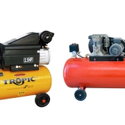
Types of Air Compressor
A compressor increases the pressure of a gas. It reduces the volume of the gas and increases its density without turning that gas into a liquid. Compressors can do this in a number of ways.
However, the commonality between all compressors is the fact that they all use some sort of fuel, such as gasoline or electricity, to power whatever compression method they use.
Also, because the compressor increases the pressure on the gas, it increases the temperature of the gas. Many other types of compressors are used for various chemicals and fuels that require compression.
There are three popular Types Air Compressor :
- Reciprocating compressor
- Screw compressor
- Centrifugal compressor
They are often some of the most critical and expensive systems at a production facility and deserve special attention. Gas transmission pipelines, petrochemical plants, refineries, and many other industries all depend on this type of equipment.
Due to many factors, including but not limited to the quality of the initial specification/design, adequacy of maintenance practices and operational factors, industrial facilities can expect widely varying lifecycle costs and reliability from their own installations.
Various compressors are found in almost every industrial facility. Types of gases compressed include the following:
- Air for compressed tool and instrument air systems
- Hydrogen, oxygen, etc. for chemical processing
- Light hydrocarbon fractions in refining
- Various gases for storage or transmission
- Other applications
There are two primary classifications of industrial compressors: intermittent flow (positive displacement), including reciprocating and rotary types; and continuous flow, including centrifugal and axial flow types.
Reciprocating compressor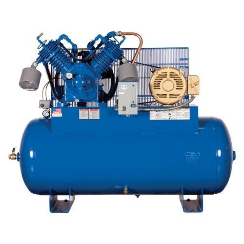
A reciprocating compressor is a positive-displacement machine that uses a piston to compress a gas and deliver it at high pressure.
Reciprocating compressors are typically used where high compression ratios (ratio of discharge to suction pressures) are required per stage without high flow rates, and the process fluid is relatively dry.
Wet gas compressors tend to be centrifugal types. High flow, low compression ratio applications are best served by axial flow compressors. Rotary types are primarily specified in compressed air applications, though other types of compressors are also found in air service.
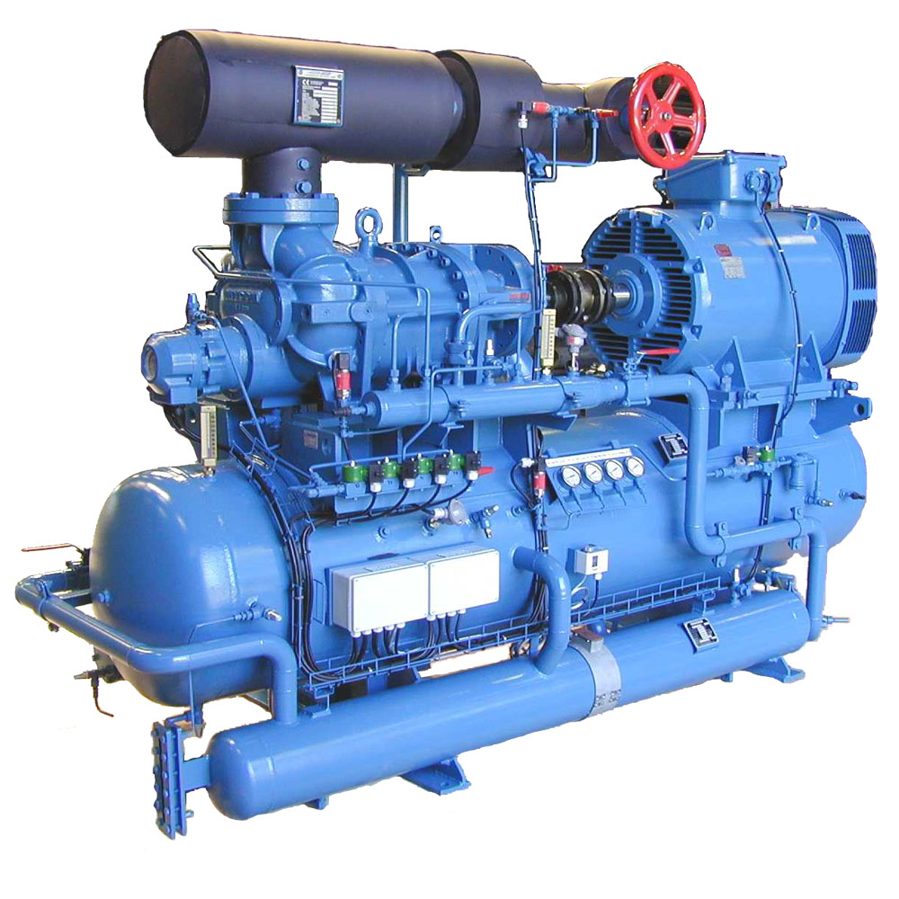
Screw Compressor
A screw compressor is a type of gas compressor that works on a rotary-type positive-displacement mechanism. A rotary screw compressor is commonly used to replace piston compressors wherein a large volume of high-pressure air is needed, either in large industries or to operate high power air tools. Oil-injected screw compressors are ideal for various industries and assembly production. With a capacity ranging from 7.5 KW to 37 KW, Mark Compressors provide you the best range of compressors. They have a simple LCD display control system, user-friendly design, uncompromised quality, and durability, and they even guarantee lasting performance. An oil-injected screw compressor can be used in the following industries,
- Wastewater Treatment
- Rubber and Plastics
- Automotive
- Apparel
- Agriculture
- Power Generation
- Petroleum
- General Manufacturing & many more.
Centrifugal Compressor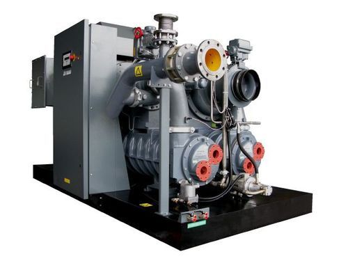
A centrifugal compressor is a type of dynamic compressor, or turbocompressor, with a radial design. Unlike displacement compressors that work at a constant flow, dynamic compressors work at constant pressure and the performance is affected by external conditions such as changes in inlet temperatures.
Air is drawn into the center of a rotating impeller with radial blades and is pushed toward the center by centrifugal force. This radial movement of air results in a pressure rise and the generation of kinetic energy. Before the air is led into the center of the impeller, the kinetic energy is also converted into pressure by passing through a diffuser and volute.
Each stage takes up a part of the overall pressure rise of the compressor unit. Depending on the pressure required for the application, a number of stages can be arranged in a series to achieve a higher pressure. This type of multi-stage application is often used in the oil and gas and process industries. Alternately, in wastewater treatment plants, low pressure, single-stage applications are used to achieve the desired pressure ratio.
In modern configurations of centrifugal air compressors, ultra-high speed electric motors are used to drive the impellers. This results in a compact compressor without a gearbox and associated oil-lubrication system, thus making it oil-free and appropriate for applications that require 100 percent oil-free air.

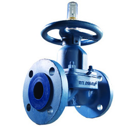
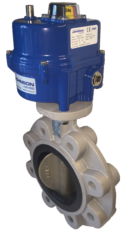 1-Electric Valves Actuators
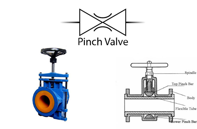
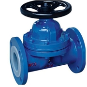
 Pinch valves benefits