Rising Stem Ball Valves

RISING STEM BALL VALVES Flowserve

RISING STEM BALL VALVES Flowserve

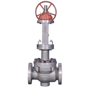
Valbart RSBV Rising Stem Ball Valves are the oil and gas industry’s choice for applications requiring a mechanically energized metal or soft seat to prevent losses from process contamination or material leakage. They are ideal for frequent cycling.

The RSBV uses a unique helix system that opens and closes the valve without rotation. The linear only operation of the stem makes it an excellent choice for frequent cycling. Each linear operation, from opening to closing and back again, is a friction-free movement between seat and ball that significantly reduces valve wear and keeps routine maintenance to a bare minimum. The outside yoke and screw, with stuffing box-type gland packing, including gland and gland flange, eliminates the need for special tools when adjusting or repacking the stem seal. Top entry convenience allows visual inspection inside the valve without removing the valve from the pipeline. The stem also has a backseat to prevent possible blowouts and repacking stem seals under pressure when the valve is fully open. A special lapping technique applied to the Stellite6® ball and seat sealing areas allows for zero seat leakage. Heavy wall thickness provides extra corrosion allowance to reduce wear and extend the valve lifetime

Industries

  • General Industry
  • Chemicals
  • Water
  • Oil & Gas
  • Power
  • Basic (Organic & Inorganic)
  • Biofuels
  • Petrochemicals
  • Waste Water
  • Agriculture
  • Upstream Exploration & Production
  • Midstream Transportation
  • Downstream Processing
  • Conventional Steam

Standards

  • API 6D/API 6FA-607/FCI 70-2
    NACE MR0175/API 598

Size Range

  • DN 25 to 600
  • NPS 1 to 24

Pressure Class Range

  • PN 10 to 320
  • Class 150 to 2500

Seating Material

  • Metal or soft

Features and Benefits

  • Extended service life and low maintenance costs due to unique helix coil stem design, which enables friction-free opening and closing
  • Improved product quality, efficiency, and safety with tightness performance up to ANSI FCI-70-2 Class VI
  • Easy in-line inspection and maintenance enabled by top-entry design
  • Reduced corrosion due to heavy wall thickness in excess to ASME/ANSI B16.34
  • Improved personnel safety from blowout-proof stem that meets international standards of API 600 and 6D

Other Features

  • Combination of a quarter-turn ball valve with a linear movement of non-rotating stem
  • Trunnion mounted design
  • Reduced or full bore
  • Single-seat (no valve body cavity)
  • Unidirectional or bidirectional
  • Metal to metal seat with stellite welding overlay (soft seat insert on request)
  • Outside screw and yoke for adjusting of stem packing
  • Blowout proof stem
  • Suitable for very high frequent cycling operations (switching valves)
  • Tight shut-off by means of application of external mechanical force and not dependent on differential pressure
  • Proper selection of materials to avoid galling and high friction
  • Protected lower trunnion against solid particles intrusion
  • Clearance control to consider high/low-temperature shrinkages
  • Self-cleaning closure member

Data Sheet

Differential Pressure Controller

Differential Pressure Controller

Series DH3 Digihelic® Differential Pressure Controller

Digital indicators are for the difference between two pressures. The Gages and Switches are ideal for pressure, velocity, flow applications, and single pressure. The Series DH3 Digihelic® Differential Pressure Controller is a 3-in-1 instrument possessing a digital display gage, control relay switches, and a transmitter with current output all packed in the popular Photohelic® gage style housing.

Combining these 3 features allows the reduction of several instruments with one product, saving inventory, installation time and money. The Digihelic® controller is the ideal instrument for pressure, velocity and flow applications, achieving a 1% full-scale accuracy on ranges down to the extremely low 0.25″ w.c. to 2.5″ w.c. full scale. Ranges of 5″ w.c. and greater maintain 0.5% F.S. accuracy. Bi-directional ranges are also available.

The Series DH3 Digihelic® controller allows the selection of pressure, velocity or volumetric flow operation in several commonly used engineering units. 2 SPDT control relays with adjustable dead bands are provided along with a scalable 4-20 mA process output.

Programming is easy using the menu key to access 5 simplified menus which provide access to security level; selection of pressure, velocity or flow operation; selection of engineering units; K-factor for use with flow sensors; rectangular or circular duct for inputting area in flow applications; setpoint control or setpoint and alarm operation; alarm operation as a high, low or high/low alarm; automatic or manual alarm reset; alarm delay; view peak and valley process reading; digital damping for smoothing erratic process applications; scaling the 4-20 mA process output to fit your applications range and field calibration.

Specification

Service

  • Air and non-combustible, compatible gases.

Wetted Materials

  • Consult factory

Housing Material

  • Die-cast aluminum case and bezel

Accuracy

  • ±1.5% for 0.25″ and ±0.25″ w.c. ranges. Ranges 0.5″ to 5″ w.c. and corresponding bi directional (except ±2.5″ w.c.) ±1%; All other ranges: ±0.5% @ 77°F (25°C) including hysteresis and repeatability (after 1 hour warm-up)

Stability

  • < ±1% per year

Pressure Limits

  • Ranges ≤ 2.5 in w.c.: 25 psi; ±2.5″, 5 in w.c.: 5 psi; 10 in w.c.: 5 psi; 25 in w.c.: 5 psi; 50 in w.c.: 5 psi; 100 in w.c.: 9 psi

Temperature Limits

  • 32 to 140°F (0 to 60°C)

Compensated Temperature Limits

  • 32 to 140°F (0 to 60°C)

Thermal Effects

  • 0.020%/°F (0.036/°C) from 77°F (25°C). For 0.25″ and ±0.25″ w.c. ranges: ±0.03%/°F (±0.054%/°C)

Power Requirements

  • 12 to 28 VDC, 12 to 28 VAC 50 to 400 Hz

Power Consumption

  • 3 VA max

Output Signal

  • 4 to 20 mA DC into 900 Ω max

Zero & Span Adjustments

  • Accessible via menus

Response Time

  • 250 ms (damping set to 1)

Display

  • Backlit 4 digit LCD 0.4″ height LED indicators for set point and alarm status

Electrical Connections

  • 15 pin male high-density D-sub connection. 18″ (46 cm) cable with 10 conductors included

Process Connections

  • 1/8″ female NPT. Side or back connections

Mounting Orientation

  • Mount unit in vertical plane

Size

  • 5″ (127 mm) OD x 3-1/8″ (79.38 mm)

Weight

  • 1.75 lb (794 g)

Agency Approvals

  • CE

Switch Type

  • 2 SPDT relays

Electrical Rating

  • 1 A @ 30 VAC/VDC

SetPoint Adjustment

  • Adjustable via keypad on the face
Rosemount Thermocouple

Rosemount Thermocouple Temperature Sensor

Rosemount 185 Thermocouple Temperature Sensor

Meet the required standards of your process temperature measurements with the Rosemount 185 Thermocouple Temperature Sensor. Rosemount Thermocouple Temperature Sensor covers a range of temperatures and is engineered as type J, K or N thermocouples (IEC 584 Class 1) with or without a thermowell to meet a variety of application requirements. This flexible temperature measurement solution also offers many configurations, enclosure and connection head options, and remote or integral mounting designs.

The Rosemount DIN-Style Sensor and Thermowell have designs that provide flexible and reliable temperature measurements in process environments. Features include:

  • Temperature range of –196 to 450 °C for RTD, –40 to 1000 °C for thermocouple
  • Industry-standard sensor types, including RTD and thermocouple varieties
  • DIN-style design for easy mounting and replacement
  • Variety of enclosure and connection head options
  • Global hazardous-location approvals available
  • Calibration services available to give you insight to sensor performance
  • MID calibration options for custody transfer
  • Assemble to transmitter option

Specifications

Insulation Resistance

  • 1,000 MΩ minimum insulation resistance when measured at 500 Vdc and at room temperature

Certifications/Approvals

  • Hazardous location, see full specs for complete list of certifications

Lead Wires

  • PTFE insulated, 0.52 mm2 (20 AWG) stranded thermocouple wire, color-coded per IEC 584

Features

  • Sensor designed per IEC 584 to offer optimal performance
  • Sensor selections cover a wide range of temperatures from -40 to 1832°F (-40 to 1000°C) to meet process demands
  • Available in single element, dual element and isolated configurations with ungrounded junctions for adaptability
  • DIN-style sensor connection heads allow for quick mounting and replacement
  • Terminal block, flying leads and spring-loaded threaded adapters provide remote or integral mounting configuration
  • Adaptable design with a variety of enclosure and connection head options meets varying application requirements
  • Option for thermowell assembly delivers increased protection from corrosive environments
  • Global hazardous location approvals meet local requirements

Technical Specification

Model

0065

  • Pt 100 RTD (IEC 751) without thermowell

0185

  • Thermocouple (IEC 584 Class 1) without thermowell

Connection head

  • 2 1/2-in. NPT
  • M20 1.5

Temperature range

  • –50 to 450 °C (–58 to 842 °F)
  • –196 to 300 °C (–321 to 572 °F)
  • –40 to 750 °C (–40 to 1382 °F)
  • –40 to 1000 °C (–40 to 1832 °F)
  • –60 to 600 °C (–76 to 1112 °F)
  • –40 to 1000 °C (–40 to 1832 °F)

Material

  • 300 series stainless steel

What is Thermocouple

A thermocouple is comprised of at least two metals joined together to form two junctions. One is connected to the body whose temperature is to be measured; this is the hot or measuring junction. The other junction is connected to a body of known temperature; this is the cold or reference junction. Therefore the thermocouple measures unknown temperature of the body with reference to the known temperature of the other body.

Danfoss sight glasses

Danfoss sight glasses

Danfoss sight glasses SGP is a series of sight glasses for high-pressure applications. SGP is available in versions optimized for refrigerants with mineral oil e.g. HCFC, and in versions optimized for non-flammable HFC refrigerants.

SGP for food retail refrigeration is available with flare, solder and socket connections, and with and without moisture indicators.

SGP sight glass is part of the Danfoss line components program which covers a wide range of components used in refrigeration systems.

What is Sight Glass?

a sight glass is a transparent glass tube or window installed in a tank or boiler system that allows an observer to view what is happening inside the container, ensuring optimal quality and safety. Sight glasses can also serve a number of functions aside from basic viewing, but this is the most common use.

While “sight glass” is a general, overarching term, there are also several more specific terms that are used to refer to different types of sight glasses. Some of the most common types of sight glasses are outlined below.

Applications of Sight Glass

Sight glasses find application in a broad spectrum of industries, such as:

  • Pharmaceuticals
  • Biofuels
  • Food and beverage processing
  • Utilities and energy
  • Chemical/petrochemical
  • Wastewater treatment and management
  • Boiler systems
  • Industrial burners
  • Pulp and paper processors
  • Oil and gas refineries
  • Automobiles and other transport vehicles
  • Combustion equipment

Sight glass Types

  • Circular sight glass fittings
  • Sight flow indicators
  • Metaglas sight glass windows
  • Glass tube liquid level gauge and Magnetic Level gauges
  • Rectangular sight glass fittings
  • Sanitary and hygienic equipment
  • Water Treatment Sight Glass Fittings

Features and benefits of Danfoss SGP

  • Good visibility to indicate flow conditions
  • Low leakage
  • Long service life
  • Extra safety with MWP 52 bar
  • Reliability of products ensures less leakage and long lifetime
  • Fast react indicator provides early warning to prevent excessive liquid

Data Sheet