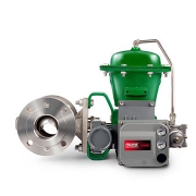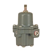
Fisher 3661 Electro-Pneumatic Positioner
Fisher 3661 Electro-Pneumatic Positioner
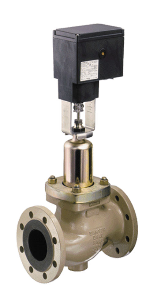
Fisher Electro-Pneumatic Positioner is used with various actuators on sliding-stem valves for throttling applications. These rugged positioners provide a valve position proportional to a pneumatic input or a standard milliampere DC input signal received from a control device.
What is a Valve Positioner?
As a common control valve accessory, the valve positioner delivers pressurized air to the valve actuator so that the position of the valve stem or shaft corresponds to the setpoint from the control system. Valve positioners are typically pneumatic or analog I/P and are used when a valve requires throttling action. They require position feedback from the valve stem or shaft and deliver pneumatic pressure to the actuator to open and close the valve
Pneumatic Valve Positioners
Legacy processing units may use pneumatic pressure signaling as the control setpoint to the control valves. In a common pneumatic positioner design, a pneumatic input signal is received from a control device and modulates the supply pressure to the control valve actuator, providing an accurate valve stem or shaft position that is proportional to the pneumatic input signal.
Analog I/P Valve Positioners
Most modern processing units use a 4 to 20 mA DC signal to modulate control valves. This introduces electronics into the positioner design and requires that the positioner convert the electronic current signal into a pneumatic pressure signal (current-to-pneumatic or I/P). In a typical analog I/P positioner, the converter receives a DC input signal and provides a proportional pneumatic output signal through a nozzle/flapper arrangement. The pneumatic output signal provides the input signal to the pneumatic positioner.
Features
- Positioner design provides accurate, fast-responding instruments able to withstand the vibrations of most plant environments. Low steady-state air consumption contributes to efficient operation.
- Easily adjustable gain and damping adjustments fine-tune the positioner stability to specific application requirements.
- The positioner accepts a standard milliampere DC input signal from a control device. This positioner provides split range capabilities and adjustable zero and spans.
- Most of the parts for 3661 positioners are interchangeable; requiring fewer spare parts to support these positioners.
- The case and cover are designed to withstand mechanical vibration and rough handling.
- Zero and span adjustments can be made with the cover in place.
- To support diagnostic testing of valve/actuator/positioner packages with the FlowScanner™ valve diagnostic system, connectors, piping, and other hardware can be installed between the 3661 positioner and the actuator.
Fisher Electro-Pneumatic Positioner Specifications
Area Classification
- Intrinsically Safe
- Non-incendive
- Dust
Certifications
- CSA
- FM
- ATEX
- IECEx
- CUTR
- Peso
- KGS
- INMETRO
- RCM
Communication Protocol
- 4-20mA Analog
Diagnostics
- No
Input Signal
- Electric
Max Outlet Pressure
- 90 psi
Mounting Type
- Actuator Mounted
Operating Temperature
- Standard Temperature
Position Control
- Modulating
Safety Certification
- NIL
Supply Media
- Air
Other Configurations
- Contact your local Emerson business partner or sales office to learn about additional specifications or options for this product.
![]()