Vortex Flow Meters Rosemount
Vortex Flow Meters Rosemount
Vortex Flow Meters Rosemount offers many advantages for flow measurement including easy installation without impulse lines, no moving parts to maintain or repair, less leak potential and a wide flow turndown range. Vortex meters also offer very low power consumption, allowing for use in remote areas.
Additionally, Vortex meters are unique in that they can accommodate liquids, gasses, steam, and corrosive applications. Vortex flowmeters are also able to withstand high process pressures and temperatures.
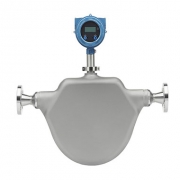
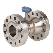
Rosemount 8800 Series Vortex Flow Meters offer world-class reliability with a gasket-free, non-clog meter body that eliminates potential leak points, resulting in maximum process availability and fewer unscheduled shutdowns. The unique design of Emerson’s Rosemount 8800 Vortex Flow Meters features isolated sensors that eliminate the need to break process seals for flow and temperature sensor replacement.
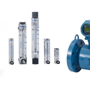
What is the Vortex flow meter?
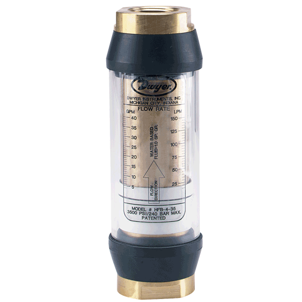
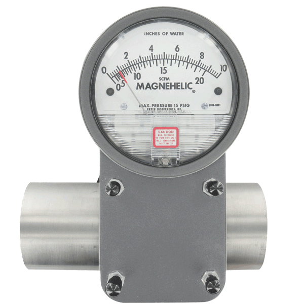
A vortex flow meter is a flow measurement device best suited for flow measurements where the introduction of moving parts presents problems. They are available in industrial grade, brass or all-plastic construction. Sensitivity to variations in the process conditions is low and no moving parts have relatively low wear compared to other types of flow meters.
Vortex flowmeters operate under the vortex shedding principle, where an oscillating vortexes occur when a fluid such as water flow past a bluff (as opposed to streamlined) body. The frequency that the vortexes are shed depends on the size and shape of the body. It is ideal for applications where low maintenance costs are important. Industrial size vortex meters are custom built and require appropriate sizing for specific applications.
Flow Meter Accuracy
- ± 0.65% of volumetric rate for liquids
- ± 1% of volumetric rate for gas and steam
- ± 0.70% of mass flow rate in water using MultiVariable option
- ± 2% of mass flow in steam using MultiVariable optio
Turndown
- 38:1
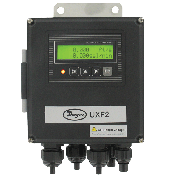
Output
- 4-20 mA with HART® 5 or 7
- 4-20 mA with HART® 5 or 7 and Scalable Pulse Output
- FOUNDATION; Fieldbus ITK6 with 2 Analog Input blocks, 1 Backup Link Active Scheduler function block, and 1 Integrator function block
Wetted Material
- Stainless Steel – 316/316L and CF3M
- Nickel Alloy – C-22 and CW2M
- High Temp Carbon Steel – A105 and WCB
- Low Temp Carbon Steel – LF2 and LCC
- Duplex UNS S32760 and 6A
- Consult factory for other wetted material
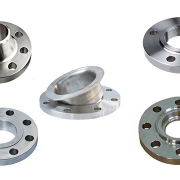
Flange Options
- ANSI Class 150 to 1500
- DIN PN 10 to PN 160
- JIS 10K to 40K
- Flanges are available in a variety of facings
- Consult factory for additional flange ratings
Operating Temperatures
- -330°F to 842°F (-200°C to 450°C)
Line Size
- Flanged: ½-in to 12-in (15 to 300 mm)
- Wafer: ½-in to 8-in (15 to 200 mm)
- Dual: ½-in to 12-in (15 to 300 mm)
- Reducer: 1-in to 14-in (25 to 350 mm)
Features
- An isolated sensor allows for inline replacement without breaking the process seal
- Increase plant availability and eliminate potential leak points with a unique gasket-free meter body design
- Eliminate downtime and maintenance costs associated with plugged impulse lines with a non-clog meter body design
- Achieve vibration immunity with a mass balanced sensor and Adaptive Digital Signal Processing with visual filtering
- A standard internal signal generator included in every meter simplifies electronics verification
- All meters arrive pre-configured and hydrostatically tested, making them ready and easy to install
- Simplify SIS compliance with available dual and quad Vortex flowmeters
- Detect liquid to gas phase change using Smart Fluid Diagnostics