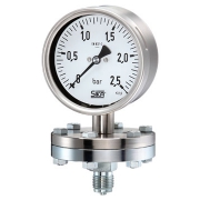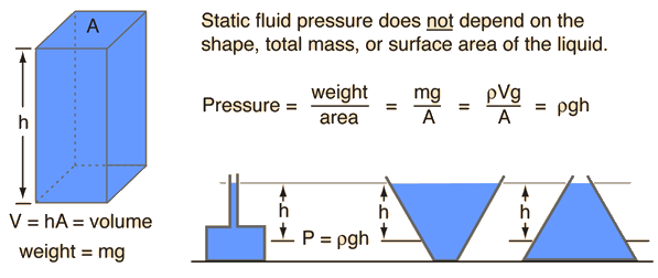
Wika Pressure Gauge 232.50
Wika Pressure Gauge 232.50
 The pressure gauge is an instrument used to measure or display pressure.Wika Pressure Gauge 232.50 is bourdon tube pressure gauges are the most frequently used mechanical pressure measuring instruments.
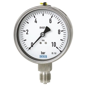
Generally, it displays pressure in Bar (Unit of Pressure). The Bourdon tube is the namesake of Eugéne Bourdon, a French watchmaker and engineer who invented the bourdon gauge in 1849. Over the years, the bourdon tube has entrenched itself as the elastic element in most pressure gauges in the application today.
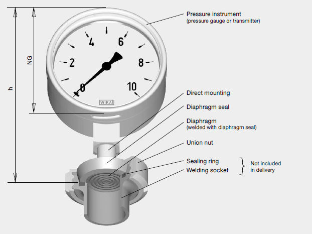
When the internal space of the bourdon tube is pressurised, the cross-section is thus altered towards a circular shape. The hoop stresses that are created in this process increase the radius of the c-shaped tube. As a result, the end of the tube moves by around two or three millimetres. This deflection is a measure of the pressure. It is transferred to a movement, which turns the linear deflection into a rotary movement and, via a pointer, makes this visible on a scale.
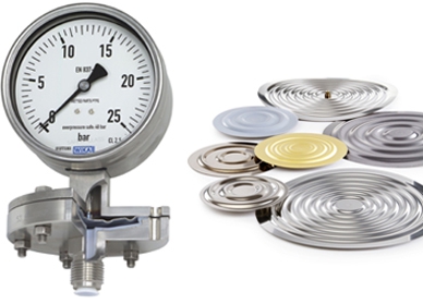
Bourdon tube variants
With the c-shaped bent Bourdon tubes, pressures up to 60 bar can be displayed. For higher pressures, helical or spiral-type Bourdon tubes are used. Depending on the geometry, material and material thickness, pressures up to 7,000 bar can be realised. Depending on the requirement, the pressure elements are made of copper alloys, stainless steels or special materials such as Monel.
The Bourdon pressure gauge operates on the principle that, when pressurized, a flattened tube tends to straighten or regain its circular form in cross-section. The Bourdon tube comes in C, helical, and spiral shapes—although most gauges employ the C shape, which is the type of Bourdon pictured at the top of the article.
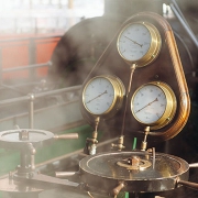
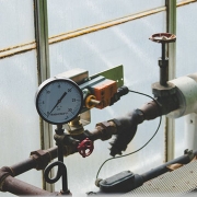
Lets start talk about the 232.50 pressure gauge from Wika.
Wika is one of the best instrumentation manufacturer in the wold.
Saba Dejlah locatated in UAE as a trading company can supply all kind of Wika products for any destination in the world.
Technical Data of 232.50
Design
- EN 837-1
Nominal size in mm
- 63, 100, 160
Accuracy class
- NS 63: 1.6
- NS 100, 160: 1.0
Scale Ranges
- NS 63: 0 … 1 to 0 … 1,000 bar
- NS 100: 0 … 0.6 to 0 … 1,000 bar
- NS 160: 0 … 0.6 to 0 … 1,600 bar
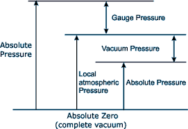
or all other equivalent vacuum or combined pressure and vacuum ranges
Pressure limitation
NS 63:
- Steady: 3/4 x full-scale value
- Fluctuating: 2/3 x full-scale value
- Short time: Full-scale value
NS 100, 160:
- Steady: Full-scale value
- Fluctuating: 0.9 x full-scale value
- Short time: 1.3 x full-scale value
Permissible temperature
Ambient:
- -40 … +60 °C without liquid filling
- -20 … +60 °C gauges with glycerine filling
Medium:
- +200 °C maximum without liquid filling
- +100 °C maximum with liquid filling 1)
Temperature effect
When the temperature of the measuring system deviates from the reference temperature (+20 °C):
- max. ±0.4 %/10 K of full-scale value
Ingress protection
- IP65 per EN 60529 / lEC 60529
Process connection
- Stainless steel 316L (NS 63: 1.4571),
- Lower mount (LM) or lower back mount (LBM), NS 63 centre back mount (CBM)
- NS 63: G ¼ B (male), 14 mm flats
- NS 100, 160: G ½ B, 22 mm flats
Pressure element
- Stainless steel 316L C-type or helical type
Movement
- Stainless steel
Dial
- Aluminium, white, black lettering,
- NS 63 with pointer stop pin
Pointer
- Aluminium, black
Case
Stainless steel, with pressure relief at case circumference, 12 o’clock (NS 63) and on the back of the case (NS 100
and 160), Scale ranges ≤ 0 … 16 bar with compensating valve to vent case
Window
- Laminated safety glass (NS 63: Polycarbonate)
Ring
- Cam ring (bayonet type), stainless steel
Filling liquid (for model 233.50)
- Glycerine 99.7 % (Glycerine 86.5 % for scale range ≤ 0 … 2.5 bar)