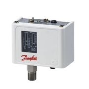
Pressure Switch
A pressure switch is a mechanical device that relies on air pressure to control the operation of an electric air compressor. This simple mechanism completes the circuit and allows power to the motor as long as system pressure is below a specified setting. All of the pressure switches used on our air compressors include a pressure switch relief valve which relieves head and line pressure, allowing for easier starts.
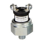
Honeywell Pressure Switch
Rely on Honeywell pressure switches to perform in critical applications that experience performance spikes and other extreme conditions. These switches sense a change in the pressure and open or close an electrical circuit when the designated set point is reached.
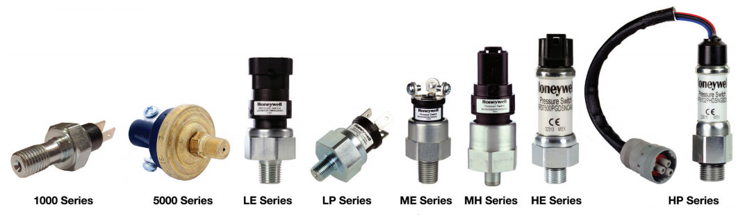
Honeywell HP Series
Honeywell HP Series pressure switches are easily customizable, durable, reliable electromechanical pressure on/off switches. They boast the following specifications:
- 100 psi to 4500 psi set point range (factory set)
- Silver and gold contacts
- 10,000 psi proof pressure (base style a); 6,500 psi proof pressure (base style b)
- 2 million life cycle (base style a); 1 million life cycle (base style b)
- SPDT, SPST-NO/NC
- Easily configurable
- Smart Diagnostic Technology option
- Hysteresis option
- Numerous ports & terminations
Honeywell HE Series
Honeywell’s HE Series pressure switches are easily customizable, durable, reliable electromechanical pressure on/off switches. They boast the following specifications:
- 150 psi to 4500 psi set point range (factory set)
- Silver contacts
- 10,000 psi proof pressure
- 1 million life cycle
- SPDT, SPST-NO/NC
- Easily configurable
- Smart Diagnostic Technology option
- Hysteresis option
- Numerous ports & terminations
Honeywell MH Series
Honeywell’s MH Series pressure switches are easily customizable, durable, reliable electromechanical pressure on/off switches. They boast the following specifications:
- Pressure switching setpoint range: 3.5 psi to 4500 psi
- Proof pressure: from 500 psi up to 10,000 psi
- Burst pressure: from 1250 psi up to 20,000 psi
- Life cycle rating up to 2 million
- IP67 sealing rating
- Operating temperature: -40 °C to 120 °C [-40 °F to 248 °F]
- Hysteresis option
- More than 15 pressure port options and over 30 electrical terminations
- Plated steel, brass or stainless steel options
- Switching point accuracy up to ±2 %
Honeywell ME Series
Honeywell’s ME Series pressure switches are easily customizable, durable, reliable electromechanical pressure on/off switches. They boast the following specifications:
- 25 psi to 350 psi setpoint range
- Gold contacts
- Factory set or field adjustable
- 4,000 psi proof pressure
- 1 million life cycle
- SPDT, SPST-NO/NC
- Smart Diagnostic Technology option
- Easily configurable
- Numerous ports & terminations
Honeywell LP Series
Honeywell’s LP Series pressure switches are easily customizable, durable, reliable electromechanical pressure on/off switches. They boast the following specifications:
- 3.5 psi to 150 psi set point range (factory set or field adjustable)
- Gold contacts
- 500 psi proof pressure
- 2 million life cycle
- SPDT, SPST-NO/NC
- Smart Diagnostic Technology option
- Easily configurable
- Hysteresis option
- Numerous ports & terminations
Honeywell’s LE Series
Honeywell’s LE Series pressure switches are easily customizable, durable, reliable electromechanical pressure on/off switches. They boast the following specifications:
- 3.5 psi to 150 psi set point range (factory set or field adjustable)
- Gold contacts
- 500 psi proof pressure
- 1 million life cycle
- Smart Diagnostic Technology option
- SPDT, SPST-NO/NC
- Easily configurable
- Numerous ports & terminations
Honeywell’s 5000 Series
Honeywell’s 5000 Series pressure switch is specifically designed to stand up to extended duty applications. This switch is factory set but capable of field adjustment. It features a Kapton diaphragm for compatibility with a wide variety of fluids and various terminations including a Metri-Pack connector that forms a tight seal when connected. Among the outstanding design, benefits are its durable construction, compact size, and enhanced set point integrity.
APPLICATIONS
- Agricultural machinery
- Heavy-duty construction machinery and trucks
- Lawn & garden machinery
- Marine vessels
- Material handling machinery
- Railway
- CNC machines
- Compressors/boilers
- Fracking equipment
- Food & beverage equipment
- Generators
- HVAC/R equipment
- Mud pumps
- Pneumatic equipment
- Presses/punches
- Pressure washers
- Trash compactors
- Water pumps & jet cutting machines
FEATURES
- Pressure switching setpoint range: 3.5 psi to 4500 psi
- Proof pressure: from 500 psi up to 10,000 psi
- Burst pressure: from 1250 psi up to 20,000 psi
- Life cycle rating up to 2 million
- IP67 sealing rating4
- Operating temperature: -40 °C to 120 °C [-40 °F to 248 °F]
- Hysteresis option5
- More than 15 pressure port options and over 30 electrical terminations
- Plated steel, brass or stainless steel options3
- Switching point accuracy up to ±2 %